THE CONTINUOUS POWER COMPANY
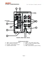
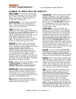
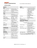
AC OUTPUT
-
A green neon lamp that will light to
indicate output power is present at the load
receptacles.
OUTPUT -
A four (4) position terminal block is
provided for the UPS output connection. Continuous
power is provided here and is monitored by the
LOAD
L.E.D.s as long as the INVERTER is
functioning. The
LOAD ON/OFF
Switch must be
enabled for power to be present here. The output
neon lamp, in the center of the panel, will be lit when
power is available.
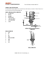
SIGNAL -
DB-9 subminiature female connectors
provided for intelligent computer monitoring
systems. See SIGNALS AND INTERFACING
Section for specific pin-outs. The top right connector
is the RS232, communications port. The other
connector has open-collector signal contacts that
generate a low state during
AC Input fail, low battery
and
UPS on.
INPUT –
A three (3) position terminal block is
provided for the UPS input connection.
DC INPUT -
An interface connector provided for
additional, external battery connections. Additional
batteries may be added to increase load run times
during a utility power failure.
SNMP INTERFACE -
(OPTIONAL) An add-on
card that provides sophisticated system network
management protocol. Direct hook-up is via an
RJ45 or BNC connector.
f the unit is to be stored, it is recommended to
refresh the internal battery at least once every
90 days. To do this, plug the system in, position
the power On/Off switch to "
ON
", press and hold
(at least two seconds) the Load On/Off Switch. Allow
the unit to run for at least 24 hours.
The
SN
unit is designed for installation in a
protected environment. Some important points to
consider when positioning a unit for operation:
A properly rated (preferably dedicated) outlet is
accessible for the six-foot power cord, supplied
with the unit. It is not recommended to modify the
supplied cord in any way nor should an extension
cord of any kind be used.
The cord paths in the system installation should
remain clear of foot traffic or anything else that
may disturb permanent connection.
The installation site should maintain an ambient
air temperature of less than 140
o
F (60
o
C). When
the environment for the system remains cooler
during operation, there is less stress on the
batteries and the internal electronics.
The air inlets, vents and fan should not be
obstructed or blocked in any way. The more
breathing space the system has, the cooler it
operates.
The air should remain free from excessive dust
and chemical fumes.
Once a location has been selected and the unit is
installed, it is ready for operation.
Allow at least 8 hours, after the system is first
installed, to fully charge the internal battery to a
maximum state.
I
INSERT INTO DOC. 510-12580-Page –12 -
INSTALLATION


