background image


Page 3 

INTRODUCTION 

ongratulations!  You have selected the 
highest quality protection for your 

continuous 

power

 needs.  This unit offers a quiet and 

compact package with superior performance you can 
depend on.  You now own a 

SP


Series


Continuous


Power System (CPS) which is an all 

Digital 

Technology

 product manufactured by 

Clary 

Corporation

, the first name in uninterruptible power 

system (UPS) reliability.  The 

Continuous Power 

System

 is the highest order in the hierarchy of UPS 

products.  When power problems occur, there can 
be no compromising the reliability of your power 
solution.  The 

SP Series


Continuous

 Power System 

is your complete power solution. 

This Owner’s Operating Manual is provided with your 
new 

SP Series UPS.  

It will enhance your 

understanding of the product and its functions.  

WE 

STRONGLY URGE YOU TO READ THIS MANUAL 
COMPLETELY, PRIOR TO BEGINNING 
INSTALLATION OR ATTEMPTING OPERATION. 

This will save you time and effort in your installation 
and application, and it will assure a trouble free 
installation and startup session, thus enhancing 
public safety and the image of your agency. 
The illustrations provided will familiarize you with this 
product’s operating modes and components. Always 
operate the unit within the guidelines and 
specifications provided to maximize safety and the 
lifetime of the unit.  Also, your understanding of the 
product is a key element in getting the most out of 
your 

SP Series UPS.


IMPORTANT SAFETY INSTRUCTIONS, 

SAVE THESE INSTRUCTIONS 

This manual contains important safety instructions that should be followed during installation and maintenance of 
the UPS and batteries.  Be aware of the following symbols and their meaning as they appear throughout the 
manual: 


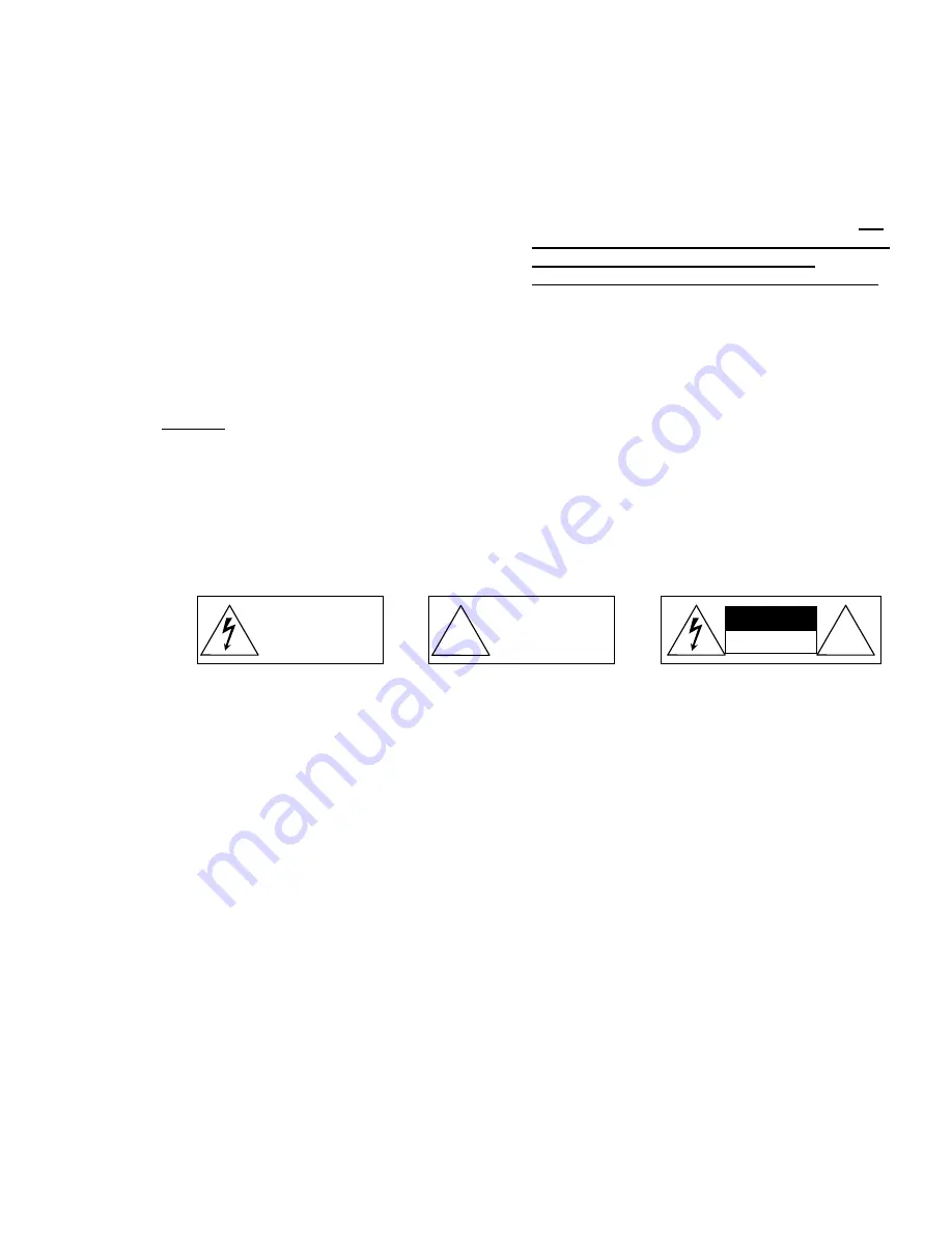
!


This symbol indicates that 
dangerous voltage constituting 
a risk of electrical shock is 
present within the unit. 

This symbol indicates that there 
are important operating and 
maintenance instructions in the 
literature accompanying this 
unit. 

!


CAUTION


RISK OF ELECTRIC 

SHOCK DO NOT OPEN 

Summary of Contents for SP1250DLE

Page 1: ...of Clary Corporation is proprietary confidential and not to be disclosed disseminated or used except for the purpose provided by CLARY CORPORATION P N 510 17582 REV PR2 Date 10 16 17 CLARY CORPORATION...

Page 2: ...AGE TABLE OF CONTENTS 2 INTRODUCTION 3 TECHNICAL DESCRIPTION 4 PACKAGING 5 PHYSICAL DESCRIPTION SP1250DLE 6 INSTALLATION 10 OPERATION 11 SIGNALS AND INTERFACING 12 USB SETUP 13 SPECIFICATIONS 16 BYPAS...

Page 3: ...ON This will save you time and effort in your installation and application and it will assure a trouble free installation and startup session thus enhancing public safety and the image of your agency...

Page 4: ...in one complete power distribution and monitoring center Not only is your critical load insured of the most reliable and constant DC AC power available but the user may now continuously monitor the s...

Page 5: ...ge to the carton or if there is any physical damage to this unit report this to your carrier These units are encapsulated in a protective wrap that comes apart once the product is removed from the shi...

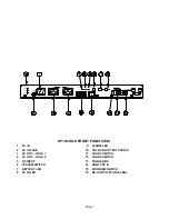
Page 6: ...Numbers on the drawing will correspond to the operating component s name at the bottom with a brief identification In the next section a complete explanation of all numbered items will be enhanced to...

Page 7: ...OUT LOAD 2 12 LOAD 2 SWITCH 5 DC INPUT 13 SIGNAL DB9 6 SYSTEM SWITCH 14 USB TYPE B 7 BATTERY LED 15 PROGRAM SWITCH 8 AC IN LED 16 DC OUTPUT STATUS LEDs LOAD 2 LOAD 1 AC OUT LOAD 2 FUSE 15A 120V AC IN...

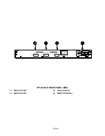
Page 8: ...Page 8 SP1250DLE REAR PANEL VIEW 17 48VDC OUTPUT 19 12VDC OUTPUT 18 24VDC OUTPUT 20 SNMP OPTIONAL DC OUTPUT 48VDC 24VDC Max Current 48 VDC 8 Amp 24 VDC 6 Amp 12 VDC 6 Amp 12VDC...

Page 9: ...voltage is available it may still be a requirement to initialize some equipment See the operations section for information on cold start Once Unit is running on AC Input this switch becomes a Battery...

Page 10: ...tion there is less stress on the batteries and the internal electronics The air inlets vents and fan should not be obstructed or blocked in any way The more breathing space the system has the cooler i...

Page 11: ...0 seconds To silence the Audible alarm quickly press and release either the Cold Start or Load button If the unit is allowed to operate further it will time out and shut off completely If power were t...

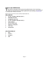
Page 12: ...niversal Traffic software which can be downloaded at www Clary com See following page for USB setup instructions Below are the pin outs of the connectors with their default assignments DB9F CONNECTOR...

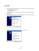
Page 13: ...0LE Software o CDC_PCDriver 2 Connect the USB cable from your computer to the UPS s USB port use the USB type B Square port 3 Turn on the UPS 4 Your computer will need a driver to connect for the firs...

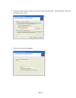
Page 14: ...Page 14 6 Select the Include this location in the search then click Browse Select the CDC_PCDriver Folder then click Next 7 The driver will then be installed...

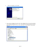
Page 15: ...device Manager then click on the Ports COM LPT tab You will see the USB CDC serial port emulation Com 1 2 3 etc This will be the com port assigned to your USB port This is the Com port you will use wh...

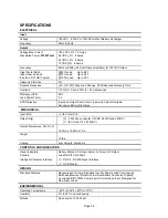
Page 16: ...ircuit Input and Output Overload Excessive Battery Discharge MECHANICAL Input Qty 1 IEC Inlet C14 Output Qty 3 2 Position connector 12VDC 24VDC and 48VDC 1 IEC Outlet C13 120VAC Overall Dimensions W x...

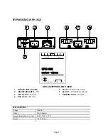
Page 17: ...AKER 15A 6 AC OUT 3 Position Connector 3 UPS AC OUT IEC C14 7 GENERATOR IN IEC C14 4 UPS AC IN IEC C13 SPECIFICATIONS Voltage 120VAC Current 30A in Bypass Overall Dimensions W x D x H 5 25 x 7 50 x 1...

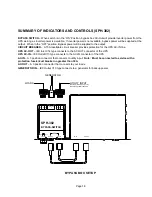
Page 18: ...AC OUT IEC Inlet C14 type connects to the AC OUT connector of the UPS UPS AC IN IEC Outlet C13 type connects to the AC IN connector of the UPS AC IN A 3 position connector that connects to utility inp...

Page 19: ...ful to the skin and eyes It may be toxic CAUTION A battery can present a risk of electrical shock and high short circuit current The following precautions should be observed when working on batteries...

Page 20: ...e factory always have the unit model number and serial number at hand This information is located on the identification label and is essential in retrieving your unit s performance and history record...

Page 21: ...sive carrier available or via customer s shipping instructions 2 3 The nature of certain equipment installations may be such that it would be impractical or technically infeasible to remove the Clary...

Reviews: