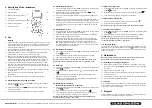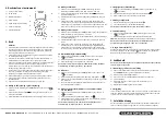
4. Description of the instrument
1) 3 ½ digit LCD display
2) OFF/ON button
3) Measurement function selector
4) Rubber case
5) Hold button (save measurement value)
6) Output for testing cables
7) Condenser socket
5. Use
Warning
1) Always check before voltage measurement that the instrument is set to the
correct measurement range and is not set to voltage or resistance or LED
measuring. Make sure you always use the correct output for the kind of
measuring that will take place.
2) Be very careful when measuring voltage which exceeds 50 V. In particular,
from measurement objects with a high output.
3) Always check that the circuit is not powered before connecting testing
cables, along with circuits (e.g. when measuring current).
4) Make sure the circuit being tested is not powered before measuring
resistance or buzzer/LED test. Make sure that the correct function and
measurement range are selected. If you are unsure which is the correct
measurement range begin with the highest and work your way down.
5) You should be very careful when using the instruments on an inductive
component. For example, transformers, relay coils or similar devices. A
high voltage level may occur (be induced) at the measuring points as the
electrical circuit is interrupted.
6) Make sure the testing cables are in good condition and that the insulation
is not damaged.
7) Make sure you do not exceed the overload limit indicated in the
specifications.
8) Fuses to be changed must be of the correct type and correct value.
5.1 Measuring direct voltage and AC voltage
1) Connect the black testing cable to the
COM
contact and the red testing
cable to the
VΩ
contact.
2) Set the function selector to
V
all measuring direct voltage or
V ~
all
measuring AC voltage.
3) Connect testing cables to voltage source or load to be measured.
5.2 Measuring direct current
1) Connect the black testing cable to the
COM
contact and the red testing cable
to the
mA
contact (for measuring between 0–200 mA).
2) Set the function selector to desired measurement Range
A
(Violet
Range on measurement function selector).
3) Connect in series testing cables between current sources and loading to be
measured.
4) When measuring current between 200 mA and 20 A (without fuse) follow the
method above. But connect the red testing cable to the 20 A contact. When
measuring high currents the instrument may only be connected a short while
(15 seconds at 20 A). This is in order to avoid overheating the shunt in the
instrument.
5.3 Measuring AC current
1) Connect the black testing cable to the
COM
contact and the red testing cable
to the
mA
contact (for measuring between 0-200mA).
2) Set the function selector to desired measurement range
A~
(the little blue
Range on measurement function selector).
3) Connect in series testing cables between current sources and loading to
be measured. When measuring current between 200 mA and 20 A (without
fuse) follow the method above. But connect the red testing cable to the
20 A
contact. When measuring high currents the instrument may only be
connected a short while (15 seconds at 20 A). This is done in order to avoid
overheating the shunt in the instrument.
5.4 Resistance measurement
1) Connect the black testing cable to the
COM
contact and the red testing cable
to the
VΩ
contact.
2) Set the measurement function selector to desired resistance range
Ω
.
3) Connect the testing cables to the circuits to be tested.
Warning: Check before measurement that the object to be tested is not
powered. Maximum overload for the input: 250 V < 30 seconds under.
5.5 Diode test
1) Connect the black testing cable to the
COM
contact and the red testing cable
to the
VΩ
contact.
2) Set the measurement function selector on
on the blue range (the same
as ).
3) Connect the black testing cable and red testing cable to anode (+) and
cathode (-) on the diode to be tested.
4) Record value for forward voltage loss on the display. If the display reads “1”:
try reversing the polarity of the
diode.
5.6 Measuring closed circuits
(method to check breaks in a cable etc.)
1) Connect the black testing cable to the
COM
contact and the red testing cable
to the
VΩ
contact.
2) Set the measurement function selector on
(the same as ).
3) Connect the testing cables to the circuits to be tested. If the resistance is
lower or almost the same as 60 Ω the buzzer is activated.
Warning: Check that the circuit to be tested is not powered. Maximum
overload for the input: 250 V < 30 seconds.
5.7 Square wave generator
1) Connect the black testing cable to the
COM
contact and the red testing cable
to the
VΩ
contact.
2) Set the measurement function selector to desired frequency Range
OUT
.
3) Connect the testing cables to the component to be tested.
5.8 Capacitance measurement
1) Set the measurement function selector to desired capacitance .
2) Insert condenser in condenser socket
Cx
.
Warning: make sure the condenser being tested has been discharged.
5.9 Frequency measurement
1) Connect the black testing cable to the
COM
contact and the red testing cable
to the
VΩ
contact.
2) Set the measurement function selector to desired frequency range
Hz
.
ATTENTION:
Never exceed limit values for voltage shown below.
Warning: Check that the circuit to be tested is not powered. Maximum
overload for the input: 250 V rms < 30 seconds.
5.10 Save data (Hold)
The ”Save data” button (Hold) is used to store data during measurement. Press
the button and you save the measurement value and
H
is displayed on the left-
hand side of the screen. The measurement value is erased when you press the
button one more time.
6. Maintenance
Warning: To avoid electric shock, remove testing cables from powered
measurement circuits before changing a battery or fuse.
6.1 Installing and changing battery/fuse
1) Make sure the instrument is not connected to a measurement circuit. Turn
the instrument off using the
POWER
button and remove testing cables from
the outputs.
2) Begin by removing protective casing.
3) Unscrew the three screws to the back piece on the back of the instrument.
4) Lift away back piece.
5) Change battery or fuse the type recommended under point 3. Specifications.
6) Put on back piece and tighten the screws.
6.2 Cleaning
Wipe instrument regularly with a damp cloth coated in mild cleaning solution. Do
not use abrasives or solvents. Make sure that no water gets into the instrument
causing short circuits or other damage.
7. Disposal
Follow local ordinances when disposing of this product. If you are unsure about
how to dispose of this product contact your municipality.
GREAT BRITAIN
For consumer contact, please visit www.clasohlson.co.uk and click on customer service.
1
2
3
7
4
5
6


