background image


9

PROTECTION CIRCUIT 


The Classé 

CAM200

 equipped with a rail currents sensors to protect the output drivers under 

extreme condition such as short output, and Mosfet fuses (2AG 1/2 PT, 1/2 amp fast blow) to protect 

the Mosfets, which are used as pre-drivers for the output stage of the amplifier. 

Also the CAM200 has an output DC sensor; this will put the CAM200 on protection mode in the 

event DC occurs at the output of the amplifier or heavy clipping of output signals. There is also an 

AC line fuse protecting the unit. It is located at the back of the unit immediately above the AC 

receptacle (see fig.1, page 10). 


If the protection circuit of the unit is triggered or any of the fuses has blown, the FRONT 

PANEL POWER LED will go to BLINKING GREEN, indicating a “fault” condition. 


WHEN THE PROTECTION CIRCUIT HAS BEEN TRIGGERED, UNPLUG THE AMP 

FROM THE OUTLET. Check for any possible event that might trigger the protection circuitry such 

as short output, blown Mosfet fuses, etc.  After the situation which has triggered the protection 

circuit has been clearly identified and corrected, attempt to re-start the unit. IF THE UNIT STILL 

GOES INTO PROTECTION MODE, OR IF IT APPEARS THAT PROTECTION FUSES DID 

BLOW, CONTACT YOUR LOCAL DEALER. DO NOT TRY TO CHANGE A BLOWN FUSE. 

REPLACING A FUSE WITHOUT CHECKING FOR COMPONENT FAILURE COULD 

RESULT IN FURTHER, SERIOUS


DAMAGE TO VITAL COMPONENTS IN YOUR 

AMPLIFIER.

 CONTACT YOUR LOCAL DEALER or Customer Service at the Classé Audio, 

Inc ---(514) 636 63 84.


Summary of Contents for CAM-200

Page 1: ...OWNER S MANUAL CAM 200 Mono Power Amplifier ...

Page 2: ... preamps are the same The same circuit is tailored to different power levels etc Differences between less expensive models and more expensive models are parts quality and compliment power supply extravagance and the amount of filtering etc as well as features and packaging This means that for years Classé has been constantly fine tuning and upgrading this circuit and its application thus reaching ...

Page 3: ... CAM200 OWNER S MANUAL TABLE OF CONTENTS UNPACKING SET UP 4 GENERAL CONNECTIONS 5 CONNECTIONS FOR REGULAR OR BALANCED INPUTS 8 PROTECTION CIRCUIT 9 CAM200 BACK VIEW 10 CAM200 TOP VIEW 11 SPECIFICATIONS 13 ...

Page 4: ...end the optional CLASSÉ REFERENCE A C Consult your dealer regarding this accessory The power transformer in the CAM200 is located at the front center of the unit Ideally a few feet should separate this area from components which are potentially could pick up hum These include preamplifiers turntables and interconnect cables In terms of providing adequate airspace for cooling a good rule of thumb i...

Page 5: ...ERCONNECT CABLES BETWEEN THE ELECTRONICS BEFORE CONNECTING THE A C LINECORDS TO THE WALL OUTLETS THIS WILL REDUCE THE POTENTIAL SHOCK HAZARD Input and output connectors are clearly marked on the back of the amplifier Use only high quality interconnect and loudspeaker cables and make all connections tight If the RCA input plugs are loose remove them and pinch down the ground leaves slightly with pl...

Page 6: ...so that it would be the 2nd 3rd 4th 5th or 6th amps to be turned on in sequence you have to follow this procedure J3 J2 J1 J0 ADDRESS RC Button Auto ON Note X X X X 0 Amp 1 No Default setting X X X out 1 Amp 2 No X X out X 2 Amp 3 No X X out out 3 Amp 4 No X out X X 4 Amp 5 No X out X out 5 Amp 6 No X out out X 0 Amp1 No X out out out 0 Amp 1 Yes Turn on when AC is live out X X X 0 DC No DC level ...

Page 7: ...ode 5 and the command codes is as follows AMP1 _____ 24 AMP4 _____ 27 AMP2 _____ 25 AMP5 _____ 34 AMP3 _____ 26 AMP6 _____ 35 These command codes will toggle the CAM200 ON OFF To turn all six of the amplifier ON and OFF the following code should be used ALL ON_____08 ALL OFF_____9 ...

Page 8: ...r to the CAM200 using balanced interconnect The XLR connector of the CAM200 is configured as below PIN 1 DRAIN PIN 2 POSITIVE NON INVERTED SIGNAL HOT PIN 3 NEGATIVE INVERTED SIGNAL All Classé preamplifiers and amplifiers have the same pin out configuration of the XLR Other manufacturers may have different XLR pin out configuration please contact the manufacture if you wish to maintain absolute pha...

Page 9: ...of the unit is triggered or any of the fuses has blown the FRONT PANEL POWER LED will go to BLINKING GREEN indicating a fault condition WHEN THE PROTECTION CIRCUIT HAS BEEN TRIGGERED UNPLUG THE AMP FROM THE OUTLET Check for any possible event that might trigger the protection circuitry such as short output blown Mosfet fuses etc After the situation which has triggered the protection circuit has be...

Page 10: ...Fig 1 CAM200 back view 10 ...

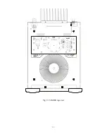
Page 11: ...Fig 2 CAM200 top view 11 ...

Page 12: ...12 CLASSÉ AUDIO 5070 François Cusson Lachine Quebec Canada H8T 1B3 Telephone 514 636 63 84 Fax 514 636 14 28 ...

Page 13: ...acteristics True symmetrical differential amplifier circuits from input to output Thick brushed Soft Shadow Silver faceplate with Satin Black middle plate CAM200 SPECIFICATIONS Frequency response 20 Hz to 20 kHz 0 1 dB Sensitivity 1 Volts in for rated output Input Impedance 75 Kohms Output Impedance 0 017 Ohm Gain 29 02 dB S N Ratio 135 dBR THD N 0 004 Rated Output 8Ohms 200Watts 4 Ohms 400Watts D...

Page 14: ...he European Community CE mark This means that your Classé product has been subjected to the most rigorous manufacturing and safety tests in the world and have proven to meet or exceed all European Community CE requirements for unit to unit consistency and consumer safety All of us at Classé Audio wish you many years of musical enjoyment As of July 18 1996 Classé Audio has been granted Certificate ...

Reviews: