background image

CP-65

Classé

PREAMPLIFIER

SERVICE MANUAL

v 1.0

Summary of Contents for CP-65

Page 1: ...CP 65 Class PREAMPLIFIER SERVICE MANUAL v 1 0...

Page 2: ...Index Mechanical Assembly 3 PC Boards 17 Testing Procedures 30 Diagrams 33...

Page 3: ...CP 65 MECHANICAL ASSEMBLY...

Page 4: ...MS 2347 PHILIPS 2 L1A2XR01 3 L1A3XR02 CP 65 FACE PLATE ASSEMBLY Class 1 M O DEL CP 65 M O DEL CP 65 STANDBY STANDBY SELECTO R SELECTO R TAPE TAPE M UTE M UTE 3 1 2 O UTPUT1 O UTPUT1 O UTPUT2 O UTPUT2...

Page 5: ...FACE PLATE ASSEMBLY 1 2 3 4 5 L214XR01 S 6 Class 2 1 2 3 6 5 4 TOP VIEW SIDE VIEW 1 SIDE VIEW 2 CP 65...

Page 6: ...CHASSIS REAR VIEW 1 2 3 4 5 6 7 8 Class 3 CP 65...

Page 7: ...CHASSIS 1 PLA CAPFR1 2 HDW 8 FLAT WASHER 3 BZO 8 32x3 4 BHCS 4 Class 6 1 2 3 4 TOP VIEW CP 65...

Page 8: ...SHIPPING AREA FINAL ASSY 1 2 Class 9 M O DEL CP 6 5 M O DEL CP 6 5 ST AN DBY ST AN DBY SELE CTO R SELE CTO R TA PE TA PE M UTE M UTE 2 1 CP 65 O UTP UT1 O UTP UT1 O UTP UT2 O UTP UT2...

Page 9: ...CP 65 PC BOARDS...

Page 10: ...MAINBOARD Class 10 CP 65 N A...

Page 11: ...CP 65 TESTING PROCEDURES...

Page 12: ...Class 14 START UP CP 65 N A...

Page 13: ...CP 65 DIAGRAMS...

Page 14: ...B2BXR00 Class 16 CP 65...

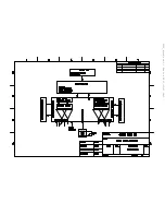
Page 15: ...CP65_block sch 1 Thu Jun 20 11 11 21 2002...

Page 16: ...B2B7XR03_amp sch 1 Thu Jun 20 11 00 56 2002...

Page 17: ...B2B7XR03_amp sch 2 Thu Jun 20 11 01 28 2002...

Page 18: ...B2B6XR00_IR_input sch 1 Thu Jun 20 10 59 40 2002...

Page 19: ...B2B5XR01_Encoder sch 1 Thu Jun 20 10 59 01 2002...

Page 20: ...B2B4XR01_display_5_button sch 2 Thu Jun 20 11 07 05 2002...

Page 21: ...B2B4XR01_display_5_button sch 1 Thu Jun 20 11 08 57 2002...

Page 22: ...B2b2XR00_line input2 sch 1 Thu Jun 20 10 56 01 2002...

Page 23: ...B2B1XR02_mother_PCB_with cs3310 sch 1 Thu Jun 20 10 51 01 2002...

Page 24: ...B2B1XR02_mother_PCB_with cs3310 sch 2 Thu Jun 20 10 51 38 2002...

Page 25: ...B2B1XR02_mother_PCB_with cs3310 sch 3 Thu Jun 20 10 53 20 2002...

Page 26: ...B2B1XR02_mother_PCB_with cs3310 sch 4 Thu Jun 20 10 54 28 2002...

Page 27: ...B2B1XR02_mother_PCB_with cs3310 sch 5 Thu Jun 20 10 55 06 2002...

Page 28: ...B2B8XR02_ext ps sch 1 Thu Jun 20 11 13 08 2002...

Page 29: ...you the complete layout of the main unit and a highlighted area in which the firmware IC U503 is located U503 is located in the center of figure 2 and above C340 and C317 when looking at the unit with...

Page 30: ...ariac to 60 vac Check the polarities 3 Crank unit to 120 vac full blast Measure all voltages as follows a Q8 IN 18 VDC OUT 14 VDC R13 13 VDC b D1 12 VDC c Q1 IN 27 8 VDC OUT 18 VDC d Q2 IN 27 8 VDC OU...

Page 31: ...ents cold solders solder bridges solder splashes and quality of the PCB 4 PCB s must be cleaned very well 5 check balance lock if working smoothly and the same appearance 2 Electrical Test Plug the un...

Page 32: ...sure and adjust voltages as follows 1 TP1 TP2 TP12 TP11 200 mv adjust trimpot Rv103 for TP1 trimpot Rv102 for TP2 trimpot Rv203 for TP12 trimpot Rv202 for TP11 R113 R102 R213 R 202 respectively 2 BIAS...

Page 33: ...2 plug in unit 3 led of power supply lights green 4 hear relay clicks and led turns red 5 see Classe CP 65 on display 6 hear relay clicks and unit goes to standby green led lights 7 press all the swit...

Page 34: ...refer to Cp 65 Panel and Display Procedure 4 Signal Test 1 Feed input signal 1 KHZ sinewave into input 1 Connect output to the oscilloscope Turn the volume up and down Should see both outputs Check f...

Page 35: ...e control 6 Paper Works 1 turn volume up to 15 measure and record the offset voltages 2 Measure and record bias voltages 3 Measure and record the difference in right and left channels in dB 4 Measure...

Page 36: ......

Reviews: