background image

SSP-30

Classé

PREAMPLIFIER / PROCESSOR

SERVICE MANUAL

v 1.0

Summary of Contents for SSP-30 MKII

Page 1: ...SSP 30 Classé PREAMPLIFIER PROCESSOR SERVICE MANUAL v 1 0 ...

Page 2: ...Index Mechanical Assembly 3 PC Boards 12 Testing Procedures 18 Diagrams 21 ...

Page 3: ...SSP 30 MECHANICAL ASSEMBLY ...

Page 4: ...M UTE TAPE IN PUT M O DE STANDBY 1 MJ 2347P 2 L2C4XR02 3 L2C3XR02 SSP 30 FACE PLATE ASSEMBLY Classé 1 SSP 30 3 2 1 ...

Page 5: ...FACE PLATE ASSEMBLY 1 N 4K 2 SDB161PVB20F 3 Flat Washer 4 Nut 5 L2C4XR02 6 6 32 x 1 4 SHSS 7 L239XR00 Classé 2 SSP 30 1 3 4 2 5 6 7 TOP VIEW ...

Page 6: ...CHASSIS REAR VIEW 1 D501 J12 S2 15 QA 2 RCA Jack 3 4 40 x 3 8 BHCS 4 N 1K 5 656 042 6 EAC 309 7 6 32 x 3 8 BHCS Classé 3 SSP 30 2 3 7 6 4 5 1 ...

Page 7: ...CHASSIS REAR VIEW 1 4 40 x 3 8 BHCS 2 Toslink 3 XLR 4 4 40 x 3 8 BHCS 5 RS 232 6 Standoff 7 4 40 x 3 8 BHCS 8 S video Connector Classé 3 SSP 30 5 6 8 7 2 1 3 4 ...

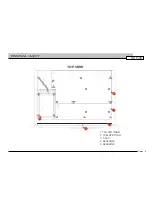
Page 8: ...CHASSIS 1 PLA CAPFR1 2 HDW 8 FLAT WASHER 3 BZO 8 32x3 4 BHCS 4 L2C1XR06 Classé 6 1 2 3 SSP 30 4 TOP VIEW ...

Page 9: ...Classé 8 PARTIAL ASSY 1 TVC STD TINAN 2 TCM STD TITAN 3 T 60C 4 B2C4XR02 5 B2CAXR00 SSP 30 TOP VIEW 2 1 4 5 3 ...

Page 10: ...SHIPPING AREA FINAL ASSY 1 L2C2XR03 2 MPF 0605 100 BO Classé 9 SSP 30 2 1 M UTE TAPE IN PUT M O DE STANDBY SSP 3 0 ...

Page 11: ...SSP 30 PC BOARDS ...

Page 12: ...B2CAXR00 SWITCH Classé 10 SSP 30 ...

Page 13: ...FRONT BOARD Classé 10 SSP 30 ...

Page 14: ...SSP 30 TESTING PROCEDURES ...

Page 15: ...from variable transformer and check the rail and driver voltages 9 If the unit is OK increase the voltage up to 120V 10 Turn off the unit and remove by pass 11 Turn on the unit and check the rails driver and offset 12 Check the sequence of relay clicking 13 Adjust the bias and offset 14 Check the protection circuit both channels 15 Check the signal with 8 and 4 load in 16 Regular regular mono bala...

Page 16: ...nels Wait 7 to 8 minutes after each adjustment Also adjust offset to 0mV 5 Measure rail and pre driver voltage 6 Measure A C voltage for bridge 7 Measure supply voltage for relays 15V and 15V for both channels 12V and 12V 8 Measure reference voltage 8 1V on both channels 9 Measure reference voltage for protection 78V 10 After setting the bias connect load and input signal Check output signal Check...

Page 17: ...SSP 30 DIAGRAMS ...

Page 18: ...uttons sch LED sand LED display leds sch Miscellaneous VF displayand IR receiver misc sch IR receiver 88 LED display Rotary ABCDEFGHIJK 1234567890 VF display shift registers Interrupt latch Parallel load Shift registers Shift registers Slot connector ...

Page 19: ...148 SW3 SW6 SW10 SW12 SW13 SW14 D15 1N4148 D16 1N4148 5D 5D 5D D17 1N4148 D18 1N4148 SW15 SW16 SW17 SW18 D24 1N4148 D25 1N4148 5D 5D 5D 5D 5D 5D 5D D26 1N4148 D31 1N4148 D28 1N4148 D29 1N4148 D27 1N4148 SW19 SW20 SW21 SW26 SW23 SW24 SW22 TapeMon 5D THX F1 F2 F3 Noise Level Distance LateNight Vol Vol Mute 5D R103 1k PRE 4 CLK 3 D 2 CLR 1 Q 5 Q 6 VCC 14 GND 7 IC7A 74HC74 PRE 10 CLK 11 D 12 CLR 13 Q ...

Page 20: ...LED34 3mmYell LED37 3mmYell THX F1 F2 F3 TP6 TP5 TP4 SERIN 14 SRCLK 11 SRCLR 10 RCLK 12 G 13 Q0 15 Q1 1 Q2 2 Q3 3 Q4 4 Q5 5 Q6 6 Q7 7 SEROUT 9 VCC 16 GND 8 IC17 74HC595 C79 100n SERIN 14 SRCLK 11 SRCLR 10 RCLK 12 G 13 Q0 15 Q1 1 Q2 2 Q3 3 Q4 4 Q5 5 Q6 6 Q7 7 SEROUT 9 VCC 16 GND 8 IC16 74HC595 C78 100n SERIN 14 SRCLK 11 SRCLR 10 RCLK 12 G 13 Q0 15 Q1 1 Q2 2 Q3 3 Q4 4 Q5 5 Q6 6 Q7 7 SEROUT 9 VCC 16 ...

Page 21: ...MOSI C71 100n SERIN 14 SRCLK 11 SRCLR 10 RCLK 12 G 13 Q0 15 Q1 1 Q2 2 Q3 3 Q4 4 Q5 5 Q6 6 Q7 7 SEROUT 9 VCC 16 GND 8 IC12 74HC595 C70 100n Optional LCD VFD connection LatchLCD LCD_D0 LCD_D1 LCD_D2 LCD_D3 LCD_D4 LCD_D5 LCD_D6 LCD_D7 LCD_RS Vcc 16 GND 8 Y0 15 Y1 14 Y2 13 Y3 12 Y4 11 Y5 10 Y6 9 Y7 7 A0 1 A1 2 A2 3 E1 4 E2 5 E3 6 IC5 74HC138 C37 100n TP2 5D TP17 TP16 TP14 TP15 TP13 TP12 TP10 TP11 R22 ...

Page 22: ......

Page 23: ... 1 8 4 IC28A TL072 R140 20k C183 33p R139 20k 5 6 7 IC27B TL072 15A R148 20k C198 33p 15A 5 6 7 IC28B TL072 R153 20k C199 33p R152 20k A B R102 20k R104 20k R98 20k R128 20k R100 20k R105 20k R125 20k R130 20k R99 20k R103 20k R127 20k R126 20k R101 20k R129 20k 3 2 1 8 4 IC19A TL072 15A R77 20k C116 33p 15A 3 2 1 8 4 IC17A TL072 R86 20k C121 33p R85 20k 5 6 7 IC19B TL072 15A R63 20k C106 33p 15A ...

Page 24: ......

Page 25: ......

Page 26: ......

Page 27: ...rd so that the connectors in line Place the new board on the standoffs making sure the connector seats properly Reinstall the four 4 hex screws Do not over tighten 5 Replace Video Board by reversing step 2 Make sure that the ribbon cables are properly aligned with the connectors on the Video Board 6 Connect the upgraded SSP 30 to the programming computer with a serial cable 9 pin and the supplied ...

Reviews: