w w w . c l a s s i c
e x h i b i t s . c o m
Step 1
Page 1 of 3
866.652.2100
© 2013
WHEN DISASSEMBLING ALUMINUM EXTRUSION, TIGHTEN ALL
SETSCREWS AND LOCKS TO PREVENT LOSS DURING SHIPPING
Order #XXXXX - Backwall Assembly
1
1
4
5
4a
6a
6b
7a
7b
8a
8b
2a
3a
5a
2
3
Item
1
2/2a
3/3a
4/4a
5/5a
6a/6b
7a/7b
8a/8b
Description
Oval Base Plate
47.5”h Round Vertical Extrusion
47.5”h Round Vertical Extrusion
47.5”h Round Vertical Extrusion
47.5”h Round Vertical Extrusion
50.875” Curved Horizontal Extrusion
50.875” Curved Horizontal Extrusion
50.875” Curved Horizontal Extrusion
Quantity
2
1
1
1
1
1/1
1/1
1/1
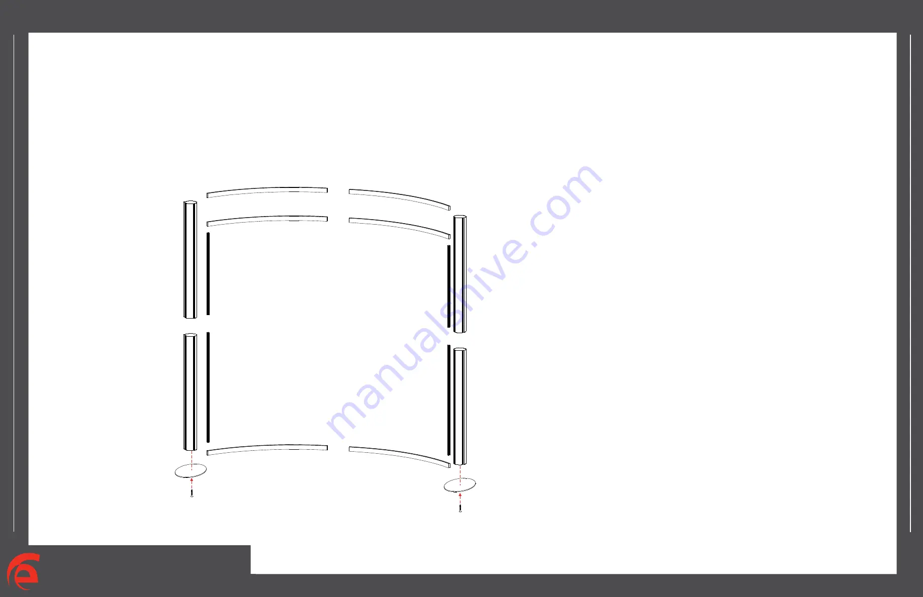
Steps:
1) Connect vertical extrusions [3 and 5] to lower vertical extrusions [2 and 4].
2) Connect vertical assemblies [2/3 and 4/5] to oval base plates [1], refer to Detail D on
General Info. Page.
3) Assemble curved horizontals by connecting pieces [6a to 6b, 7a to 7b, 8a to 8b].
4) Connect lower curved assembly [6a/6b] between vertical assemblies [4/5 and 2/3] as shown
below.
5) Connect curved assemblies [7a/7b] between vertical assemblies [4/5 and 2/3].
7) Connect curved assemblies [8a/8b] between vertical assemblies [4/5 and 2/3].
Note: Attaching Graphics
Velcro the Graphics to the Top Front Edge of
the Upper Horizontals,
to the Bottom Front Edge of the Lower Horizontals
and along both sides


