w w w . c l a s s i c
e x h i b i t s . c o m
Step 3
Page 3 of 3
866.652.2100
© 2013
WHEN DISASSEMBLING ALUMINUM EXTRUSION, TIGHTEN ALL
SETSCREWS AND LOCKS TO PREVENT LOSS DURING SHIPPING
Order #XXXXX - Pedestal Assembly
Floor
Insert
Insert
Insert
Door
Item
15
16
17
17A
18
19
20
21
22
Description
38”h Vertical Extrusion
38”h Vertical Extrusion
42”h Vertical Extrusion
Plate for Counter Connection
38”h Vertical Extrusion
20”w Horizontal Extrusion
8.5”w Horizontal Extrusion
20”w Horizontal Extrusion
8.5”w Horizontal Extrusion
Quantity
1
1
1
1
1
2
2
2
2
15
16
17
18
19
20
19
20
21
22
21
22
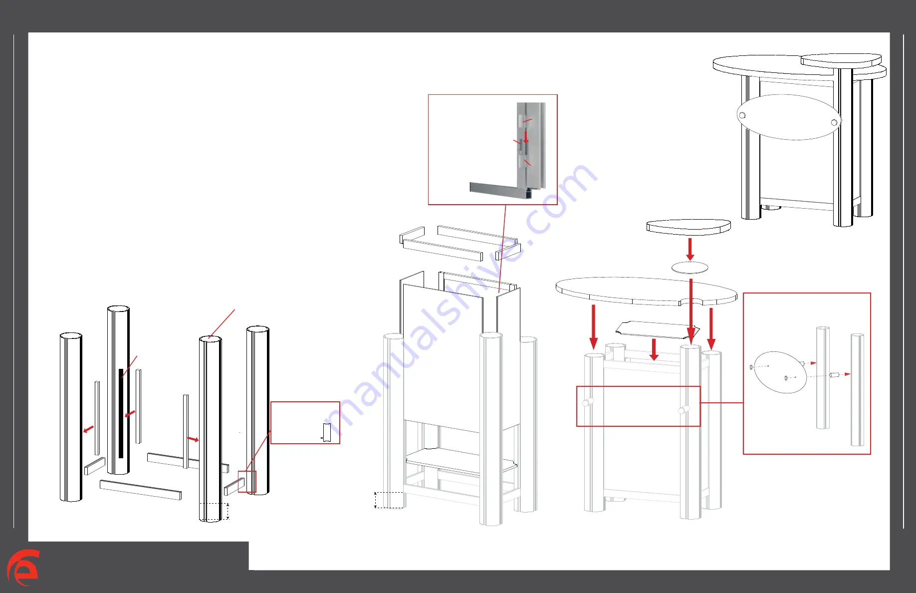
Steps:
1) Connect horizontal extrusions [19 and 20] between vertical extrusions
[15, 16, 17 and 18] at approximately 3.5” up from floor to bottom of metal.
2) Set floor in place atop lip of horizontal extrusions.
3) Place doors and inserts in place as shown.
4) Connect horizontal extrusions [21 and 22] between vertical extusions
[15, 16, 17 and 18] and atop inserts and door.
5) Velcro shelf supports to inside of pedestal, then set internal shelf atop supports.
6) Place counter atop assembled pedestal, attach [17A] to extrusion
[17] then connect smaller counter to [17A].
Plex Graphic Connection
Attach graphic using
Stand-off barrel and cap.
Extrusions 19 and
20 have a lip for
floor to rest
upon.
NOTE: TOP SIDE
Label needs to be
at top of round extrusion.
3A
17A
Internal Shelf
Slide pin into
hinge attached to
Round Vertical.
Slide Door hinge
atop pin.
Door
Hinge
Pin
Hinge
Door Attachment
Shelf
Support
Velcro
Strip
3.50”
3.50”


