III.
For tank depths of 16’’ to 21’’ no disassembly of the sender bracket is necessary.
1. Loosen two screws “d’’ and adjust the plastic housing up or down until the proper dimension from Table 1 is obtained,
then retighten screws securely.
IV.
To install the float assembly, loosen screw “h’’, remove the short piece of rod, and discard. Insert the float rod until the proper
length “c’’ from Table 1 is met, and then tighten the screw securely. Carefully cut off any excess rod with bolt cutter or similar tool,
taking care not to damage the assembly.
NOTE:
Make sure the float is installed toward the side marked “
FLOAT SIDE
”. If installed backwards, the fuel gauge will indicate
“full’’ when the tank is empty, and “empty’’ when the tank is full.
1.
Cut the bracket (
g
or
f
) so it doesn’t extend lower than the black rheostat assembly. The rheostat should be the
lowest point of the fuel sender.
2.
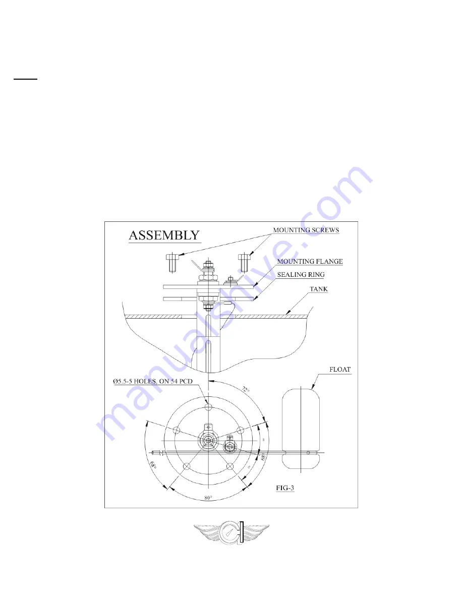
With the gasket in place below the flange, carefully feed the float arm and sender body into the 1.697’’ (43mm)
hole in the tank. Make certain the float arm has free motion within the tank. Using the sender flange as a
template, locate the position of the five mounting holes. Use the supplied screws to mount into the tank with
threaded inserts in place.
3.
Insert fuel sender assembly into tank, align holes and thread in mounting screws. Check that all screws are
secure to complete assembly.
If the float is obstructed inside the tank loosen the large nut on the center terminal
and rotate the rheostat assembly.
4.
Connect the center terminal of the sender to your fuel gauge’s signal terminal. Connect the off-center terminal to
a good chassis ground.
AVOID OVERTIGHTENING.
www.classicinstruments.com
Revision: May 22, 2014


