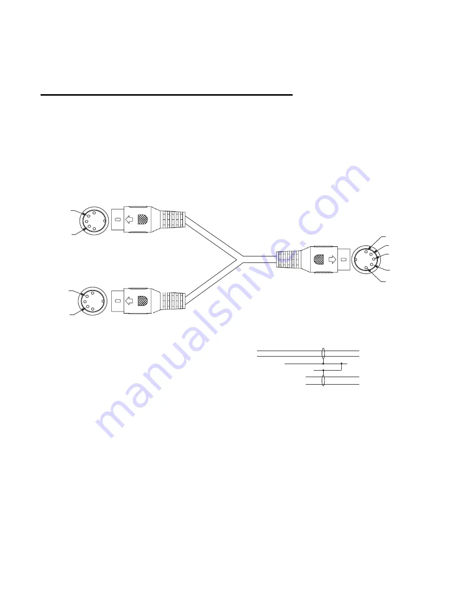
Appendix B: Bi-Directional Cable Schematic
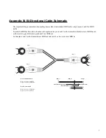
The important thing to remember when making these cables is that standard MIDI cables only use pins 4 and 5 for MIDI
traffic.
To make the MIDIjet Pros able to function with regular cables, pins 4 and 5 on the transmitter (black) unit, are MIDI In and
on the receiver (grey/white) unit, pins 4 and 5 are MIDI out.
So then pins 1 and 3 on the transmitter are MIDI out and 1 and 3 on the receiver are MIDI in
17
4
5
4
5
5
4
2
1
3
Plug 1
Plug 2
Plug 3
For a Transmitter Cable
Plug 1 - Connect to MIDI In
Plug 2 - Connect to MIDI Out
For a Receiver Cable
Plug 1 - Connect to MIDI Out
Plug 2 - Connect to MIDI In
4
5
1
3
4
5
4
5
Plug 3
Ground
Shell
Shell (Not Connected)
Shell (Not Connected)
Plug 1
Plug 2

