background image

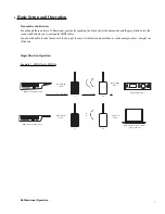
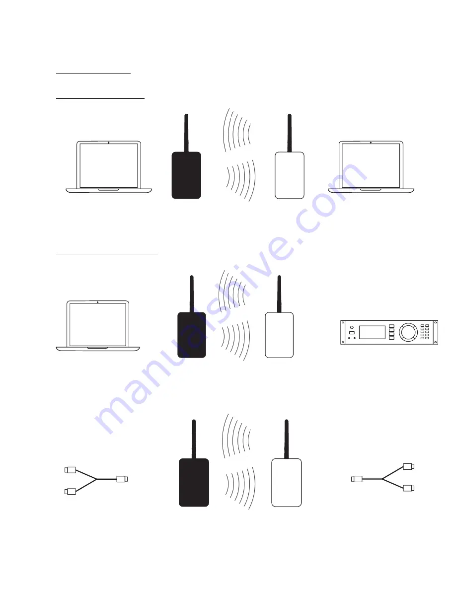
Bi-directional transmission allows MIDI traffic to flow on all 16 MIDI channels in both directions

Example 1 - USB to USB

Example 2 - USB to MIDI I/O

Example 3 - MIDI I/O to MIDI I/O

8

Bi-Directional

MIDI cable 

Tx

Rx

Bi-Directional

MIDI cable 

to MIDI In

to MIDI Out

to MIDI In

to MIDI Out

Bi-Directional

MIDI cable 

Tx

Rx

DAW or MIDI Control Software 

 I/O via USB  Port

USB A to B

cable

MIDI Device 

 I/O via In and Out Jacks

Bi-Directional MIDI Tra

ffi

Tx

Rx

links or syncs 16 channels each direction

DAW or MIDI Control Software 

 I/O via USB  Port

DAW or MIDI Control Software 

 I/O via USB  Port

Summary of Contents for WMJ-003

Page 1: ...ST PRACTICES FOR WIRELESS COMMUNICATION 10 TIPS AND TRICKS 11 EXTENDED SETUP 11 CHANNEL SELECTION 11 BINDING MIDIJET PRO SETS 12 TROUBLESHOOTING CHECK LIST 12 FIRMWARE UPDATING 13 APPENDIX A DIP SWITC...

Page 2: ...gular wear it will assess a fair repair or replacement fee The customer will have the option to pay this fee and have the unit repaired and returned or not pay this fee and have the unit returned un r...

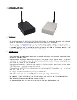
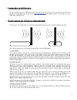
Page 3: ...Ijet Pro allows you to get off stage and interact with your fans Sure it gets rid of cables and all that but it s really about you and your fans having more fun during the show It s also about making...

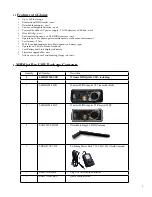
Page 4: ...battery type Operates on 2 4 GHz license free band Low Battery and Link display indicators Firmware upgradable new Allows you to do cool and amazing things not new 2 MIDIjet Pro USB Package Contents...

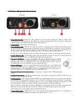
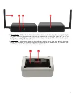
Page 5: ...ve 2 way MIDI traffic For 1 way MIDI traffic just use a regular MIDI cable 6 Receiver MIDI Jack Connect a regular MIDI cable from the MIDI Jack on your MIDI jet Pro receiver to the MIDI In jack on you...

Page 6: ...e batteries varies widely with the voltage and the capacity of the battery Some high capacity rechargables can last longer than disposable ones 12 Dip Switches The dip switches are used for setting ch...

Page 7: ...d be able to take them out of the box put in some AA batteries and use them as in the example above straight out of the box Single Direction Operation Example 1 MIDI Out to MIDI In Example 2 MIDI Out...

Page 8: ...al MIDI cable Tx Rx Bi Directional MIDI cable to MIDI In to MIDI Out to MIDI In to MIDI Out Bi Directional MIDI cable Tx Rx DAW or MIDI Control Software I O via USB Port USB A to B cable MIDI Device I...

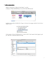
Page 9: ...our OS X Audio MIDI Setup utility On Windows based machines the MIDIjet Pro will appear in the Sound video and game controllers list in the Device Manager or in your It will also appear as Wireless US...

Page 10: ...ence is caused by conflicting radio signals emitted by other electrical products but in particular large power transformers microwaves wireless networking equipment cell phones and cordless phones emi...

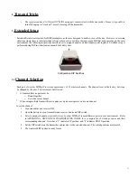
Page 11: ...wireless MIDIjet Pro system operates on 1 of 29 wireless channels The channel is set at the factory but it can be changed by the user Two rules must be followed ATransmit Receive pair must be o Bound...

Page 12: ...p this step if you are only binding a pair of MIDIjet Pros If you are binding multiple transmitters plug the next transmitter into the cable to the receiver and wait for the POWER indicator LED on thi...

Page 13: ...and transmitter and that each pair is operating on its own channel See extended setup for further details 5 Try replacing wireless MIDI adapters with standard cable If this does not work the problem l...

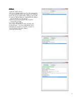
Page 14: ...pidly 5 Click the Refresh Firmware button when the software finds the MIDIjet Pro automatically 6 Wait for the Erase Program Verify Completed Successfully message 7 Close the loader software 8 Disconn...

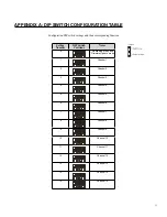
Page 15: ...nding function Setting Number DIP Switch Positions Notes 0 No Binding mode and Firmware Update mode 1 Channel 1 2 Channel 2 3 Channel 3 4 Channel 4 5 Channel 5 6 Channel 6 7 Channel 7 8 Channel 8 9 Ch...

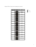
Page 16: ...DIP Switch Positions Notes 16 Channel 16 USB Interface Mode no wireless 17 Channel 17 18 Channel 18 19 Channel 19 20 Channel 20 21 Channel 21 22 Channel 22 23 Channel 23 24 Channel 24 25 Channel 25 2...

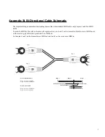
Page 17: ...black unit are MIDI In and on the receiver grey white unit pins 4 and 5 are MIDI out So then pins 1 and 3 on the transmitter are MIDI out and 1 and 3 on the receiver are MIDI in 17 4 5 4 5 5 4 2 1 3 P...

Reviews: