46
Index 1:
1. Indoor or Outdoor DC Fan Motor(control chip is in fan motor)
Measure the resistance value of each winding by using the tester. If any resistance value is zero, the
fan motor must has problems and need to be replaced.
Index2:
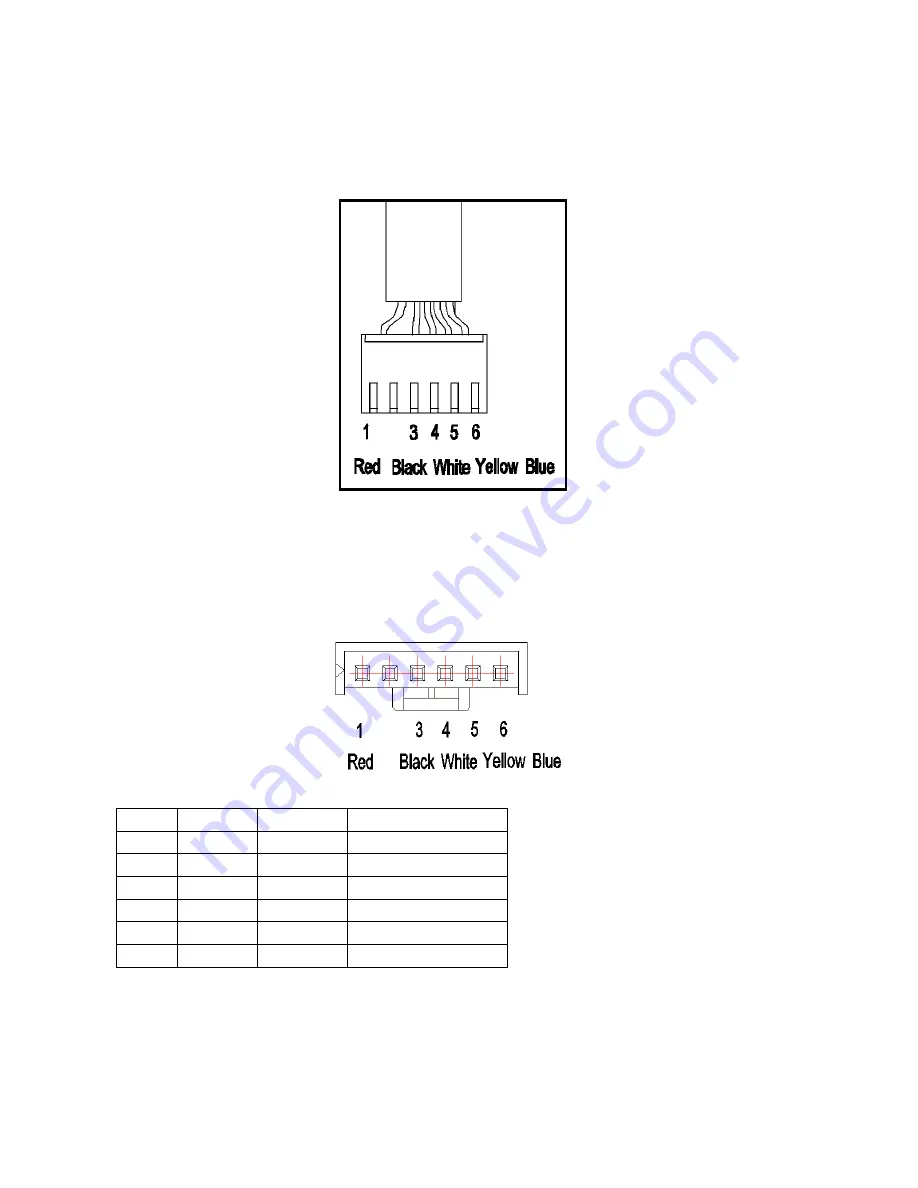
1:Indoor or Outdoor DC Fan Motor(control chip is in fan motor)
Power on and when the unit is in standby, measure the voltage of pin1-pin3, pin4-pin3 in fan motor
connector. If the value of the voltage is not in the range showing in below table, the PCB must has
problems and need to be replaced.
DC motor voltage input and output
NO.
Color
Signal
Voltage
1
Red
Vs/Vm
280V~380V
2
---
---
---
3
Black
GND
0V
4
White
Vcc
14-17.5V
5
Yellow
Vsp
0~5.6V
6
Blue
FG
14-17.5V
Summary of Contents for MROHC09AS
Page 14: ...12 5 Wiring Diagram 5 1 Indoor Unit MWOHC09S MWOHC12S MWOHC18S ...
Page 15: ...13 MWOHC24S ...
Page 16: ...14 5 2 Outdoor Unit MROHC09AS MROHC12AS ...
Page 17: ...15 MROHC18AS ...
Page 18: ...16 MROHC24AS MROHC09AS MROHC12AS ...
Page 19: ...17 MROHC18AS ...
Page 29: ...27 T2 7 C 44 6 F the compressor frequency will not be limited ...
Page 53: ...51 Take the 9k model as example P V P U ...
Page 54: ...52 N U P W ...
Page 55: ...53 N W N V ...


