background image


Chapter 3 refereNCe  

|  25


M

Roland and Yamaha are trademarks of 
their respective owners and are not af-
filiated or associated with Nord. These 
trademarks are mentioned here only as a 
reference to products that can be used 
with the Nord Drum 2.

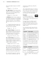
Inp Thres 

Use this setting to make sure 
that a pad or other drum unit 
mounted on the same hardware as another 
pad does not accidentally trigger a channel . 
If striking a pad that is connected to channel 
2 also triggers the sound on channel 1, raise 
the threshold on channel 1 .

Range: 

t

 . 

0 - t

 .

100

Inp Sens, Dynamics 

Input Sensitivity

 is used to 

match the output signal of the 
pad or trigger device connected to the Trig 
Input of the selected channel . 

The Input Trig Level LEDs provides informa-
tion on the trigger signals from the pads . The 
green LED will indicate that a trigger signal is 
received . The red LED will blink quickly when 
the trigger signal is 3 dB below the maximum 
and it will be lit up in a longer duration when 
the maximum signal is fed to the Trig Input . 

Adjust the Inp Sens parameter to make sure 
that only your hardest strike lights up the red 
LED in its longer duration on the Input Trig 
Level LEDs . 

Range: 

S0 - S100


Inp Thres and Inp Sens settings made 
with a Nord Pad connected will be stored 
in the unit even if you disconnect the Nord 
Pad to use (and make other Inp Thres set-
tings for) other pads. Just reconnect the 
Nord Pad to revert to those settings.

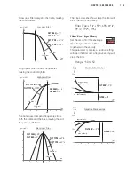
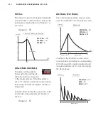
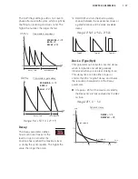
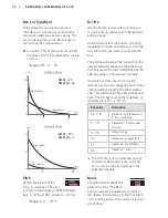
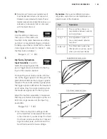
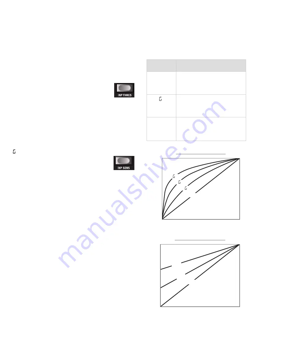
Dynamics

: there are six different dynamic 

response curves that can be individually ap-
plied to each of the channels .

Dyn

Description

d

 .

Lin

This curve has a linear cor-
respondence between velocity 
and output level .

d

 .

L 1-3

The Logarithmic curves of-
fers a compressed dynamic 
response .

d

 .

OL1-2

The Offset Level curves has 
little dynamic response, useful 
when you want even levels . 

 

 

 

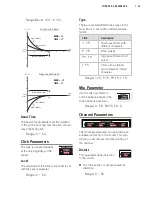
Logarithmic dynamic curves

hard

 output

level

soft

max

min

trigger input









Offset Level dynamic curves

hard

 output

level

soft

max

min

trigger input
Summary of Contents for Nord Drum 2

Page 1: ...User Manual Nord Drum 2 OS version 2 1x Part No 50416 Copyright Clavia DMI AB Print Edition B...

Page 2: ...flash with the arrowhead symbol within an equilateral triangle is intended to alert the user to the presence of uninsulated voltage within the products en closure that may be of sufficient magnitude...

Page 3: ...ode 16 Decay 17 Dec Lo Type Dyn 17 Tone Parameters 18 Spectra 18 Wave 18 Timb Env Dyn Timb 18 Timbre 19 Timb Dec Hi Decay 19 Punch 19 Decay 19 Dec Lo Type Dyn 20 Pitch 20 Scl Pre 20 Bend 20 Bend Time...

Page 4: ...he Phones output This is a 1 8 mini jack Left Right Out The L and R outputs are unbalanced jacks with line level signals E E The Nord Drum 2 is capable of produc ing sounds with a very wide dynamic an...

Page 5: ...or a slow response from the Nord Drum 2 make sure that you ad just the Trig Type Inp Thres and Inp Sens parameters Read more on how to adjust these settings on page 9 Power Connect the Nord Drum 2 po...

Page 6: ...Dial are used when you select a program and when you edit the sounds in the Nord Drum 2 Channel Select There are six channels each channel repre sents one sound Press the Channel Select buttons repeat...

Page 7: ...Dial is turned If a button activates a parameter in the up per row a quick double tap on the same button or by pressing the Row Select button will move the edit focus to the second row parameter Lowe...

Page 8: ...MIDI notes Trig Tap Trig Use the Trig Tap Trig button to trigger a selected channel Tap You can set the Echo tempo by tapping Hold the Shift and Echo BPM button and tap repeat edly on the Trig Tap Tr...

Page 9: ...at the Input Channel LEDs for that particular chan nel The LEDs indicate the strength of the incoming trigger signal from the pad 2 Hold Shift and press the Inp Sens button on the Nord Drum 2 panel Th...

Page 10: ...the Nord Drum 2 with a MIDI unit the MIDI channel and the notes that this unit transmits must be matched to the MIDI channel of the Nord Drum 2 The default Global MIDI Channel is channel 10 1 Connect...

Page 11: ...annels to the additional MIDI note numbers that the MIDI unit transmits 6 Press the Program button to Exit Changing programs Press the Program button and turn the dial to change programs Programs are...

Page 12: ...tedly on the System button until Pr On is shown in the display 2 Turn the Dial to the Pr Of setting This makes it possible to store programs until this parameter is set to On again 3 Exit by pressing...

Page 13: ...ith numbers and or characters in the display 3 Reference Channels signal flow There are six channels in the Nord Drum 2 it can produce six simultaneous sounds Each one of the channels has an identical...

Page 14: ...nd adds one or more to the right of it depending on how many times you push the button An Edit Group is needed for the Scale Preset feature Read more about this on page 20 M M Edit groups are not save...

Page 15: ...e noise filter together with the velocity This parameter is bipolar a positive setting will open the filter and a negative setting will close the filter Range 50 to 50 FILT FREQ FILT RES Low pass filt...

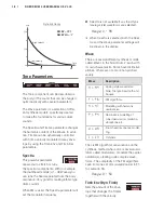
Page 16: ...take a longer time If the Atk Mode parameter is set to any of the LFO modes this parameter set the rate of the LFO Range 0 50 Atk Mode Env Mode The noise envelope attack decay can be used in a traditi...

Page 17: ...he noise envelope decay Range 0 50E 0 50L 0 50 Dec Lo Type Dyn This parameter can activate a second decay which is dynamic and will be gradually introduced when you use less striking force This decay...

Page 18: ...A type analog style waveforms are selected Range 0 99 When Spectra is selected both the Spec tra and the Wave parameter settings will be shown in the display Wave There are several different synthesis...

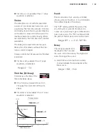
Page 19: ...envelope decay M M If the Timb Env parameter is set to 0 changing this parameter will have no effect M M Timb Dec is not available if the A 1 sine waveform is selected Range 0 50 Punch Punch can add...

Page 20: ...dit Group and increase with a factor determined by the selected scale on the selected channels If a Scale has been used to set a pitch relationship you can change the pitch of one channel without brea...

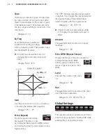
Page 21: ...hort pulses PH 1 9 High pass filtered short pulses C1 9 Clicks with a pitched and somewhat chirpy character Range n1 9 P1 9 PH1 9 C1 9 Mix Parameter Use the mix parameter to set the balance between th...

Page 22: ...o BPM buttons and turning the Dial For more repeats use a higher setting EQ FREQ Parametric equalizer 28 f c 0 24 24 GAIN GAIN freq gain dB The rEP settings indicates a fixed number of repeats If you...

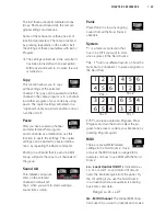
Page 23: ...that is part of an Edit Group will paste the copy to all channels in the group Sound Init This initializes all param eters on the selected channel to default set tings when you want to start creating...

Page 24: ...pies of your individual programs or to share them with other Nord Drum 2 users The transmission is activated by pressing the Program button ALL transmits all the programs in the Nord Drum 2 memory as...

Page 25: ...when the trigger signal is 3 dB below the maximum and it will be lit up in a longer duration when the maximum signal is fed to the Trig Input Adjust the Inp Sens parameter to make sure that only your...

Page 26: ...of the utility is a zipped archive when you download it from the website This archive has to be ex panded with an application like WinRAR before the utility can be executed 3 Select the MIDI ports yo...

Page 27: ...d for the computer to communicate with the Nord Drum 2 Select the MIDI Ports that the Nord Drum 2 is connected to in the Setup Dialog Get Banks Program Banks can be saved on the computer hard drive by...

Page 28: ...2 you can control all the param eters on all the Nord Drum 2 channels Recording Global MIDI Channel Connect the Nord Drum 2 MIDI In and Out to a computer MIDI interface sequencer Set the sequencer tra...

Page 29: ...rogram or record the notes on one track in the sequencer a track set to the Global MIDI Channel Create a new track that is set to the Individual MIDI channel of the Nord Drum 2 channel you wish to con...

Page 30: ...Nord Drum 2 is connected to MIDI In on a MIDI interface connected to the computer 2 Press Shift and the MIDI button repeat edly until PRo or ALL is shown in the display Selecting PRo will transmit th...

Page 31: ...ope 17 Noise Filter Resonance 18 Noise Attack Rate 19 Noise Atk Mode 20 Noise Decay Type E L G 21 Noise Decay 22 Noise Decay Lo 23 Dist Amount 24 Dist Type 25 EQ Frequency 26 EQ Gain 27 Echo Feedback...

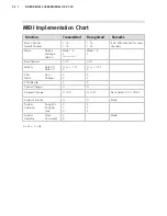
Page 32: ...hannels Mode Default Message Altered Mode 1 3 X Mode 1 3 X Note Number 0 127 0 127 Velocity Note ON Note Off O v 1 127 X O v 1 127 X After Key s Touch Channel X X X X Pitch Bender X X Control Change O...

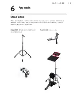
Page 33: ...ttered setup using only two pieces of standard drum hardware You can mount both the Nord Drum 2 and the Nord Pad on the same stand and adjust the height and tilt of both units 6 Appendix Roland PDS 10...

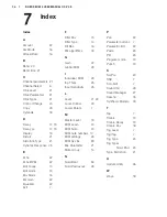
Page 34: ...lt Res 16 FM algorithms 18 G Gain 22 Global MIDI 23 I Individual MIDI 23 Inp Thres 25 Input Sensitivity 25 L Level 21 22 Local Control 23 Lower Param 7 M Master Level 13 MIDI Learn 24 MIDI Note 24 MID...

Page 35: ...or television reception which can be determined by turning the equipment off and on the user is encouraged to try to correct the interference by one or more of the following measures Reorient or reloc...

Page 36: ......

Reviews: