This section assumes that you are installing the SFB in a Clavister chassis and the chassis power is
on. The Clavister chassis architecture allows insertion and removal of blades without powering
down the system. The SFB powers up all other blades within the chassis.
The steps for installation are:
1.
Follow ESD precautions and make sure you are adequately grounded before handling the
transceivers and the SFB.
2.
Remove the SFB from its antistatic bag.
3.
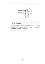
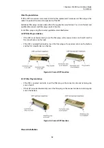
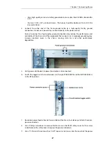
Open both ejector latches outward.
Figure 6.5. SFB Latch Open Position
4.
Slide the SFB into one of the hub slots on the chassis. The hub slots for the SC6300 Series
Chassis are numbers 1 and 2.
If correctly aligned, the edges of the SFB will fit within the narrow guide rails of the chassis.
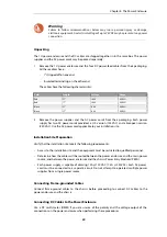
Warning
Do not force the SFB into the slot:
a.
To avoid damage to connectors, make sure the rear slot is either empty or
contains a module that is compatible with the SFB.
b.
If the SFB does not slide in easily, make sure that it is being inserted it into the
correct slot and that it is aligned properly.
5.
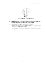
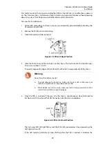
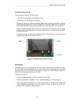
Once the SFB is inserted all the way into the chassis, simultaneously close both ejector
latches inward. This will seat the SFBs connectors into the chassis backplane.
Figure 6.6. SFB Latch Closed Position
The hot-swap (H/S) LED light flashes until the SFB is fully powered up. Once powered up, the
LED light will turn off.
If the LED remains solid blue or keeps flashing after the SFB is inserted, it indicates the
Chapter 6: SF6090 Switch Fabric Blade
Installation
19

