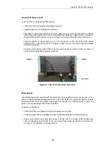
1.
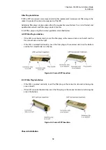
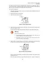
Loosen the screws on the DC cable connector on the back of the power enclosure. This
opens the slots where the cables will be inserted.
2.
Insert the stripped end of the cables into the slots that match their polarity. The red cables
typically go into the top slot and the black cables typically go into the bottom slot.
3.
Tighten the screws on the DC cable connector.
Figure 8.2. Power Rack Rear View - DC Cable Connector Detail
Connect DC cables to the Chassis
These following steps cover connecting the DC cables to the Power Entry Modules (PEMs)
located on the back of the chassis:
1.
Follow the safety precautions described previously.
2.
Verify the chassis connection to the supply circuit will not overload the circuit's overcurrent
and supply wiring. The supply should be capable of delivering the equipment nameplate
ratings of -48V@ 40A or -60V @ 40A.
3.
Switch the toggle switch circuit breakers on PEM Right (R) and PEM Left (L) to the OFF
position.
4.
Route the DC cables from the power enclosure to the area behind the chassis, but do not yet
attach them to a power connection.
The shorter length cables will route to PEM R and the longer length cables will route to PEM
L.
5.
Use a Phillips screwdriver to remove the #6 screw on the PEM's safety cover. Set the screw
aside. Remove the safety cover to expose the power connectors.
6.
Use a 7/16" wrench to remove the 1/4"-20 top nuts and washers from each of the power
connector posts on the PEM. Verify the bottom nut is still secure on the connector post. Set
the top nuts and washers aside.
7.
Connect the power-feed cables (with Panduit connector P/N LCAX8-14-L or equivalent) to
the appropriate connectors. Check the labels next to the connectors for polarity.
Chapter 8: The Power Enclosure
31


