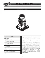
background image

ALPHA BEAM 700

6

28

28

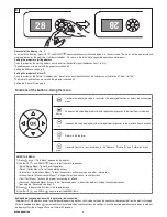
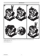
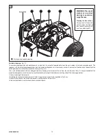
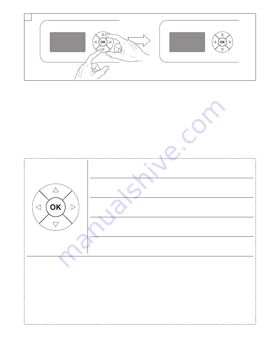
Reversal of the display - Fig. 9

To activate this function, press UP 

B

and DOWN 

C

keys simultaneously while the display is in the rest mode. This status will be memorised and

maintained even for the next time it will be switched on.  To return to the initial state, repeat the operation all over again.

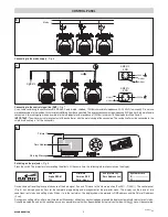
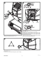
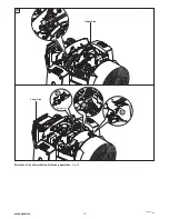
Setting the projector starting address

On each projector, the starting address must be set for the control signal (addresses from 1 to 512). 

The address can also be set with the projector switched off.

Setting the address: see pag. 8.

Setting the projector Fixture ID 

On each projector, the Fixture ID address must be set for an easy identification of the fixtures in an installation (ID from 1 to 255).

The Fixture ID address can be set with the projector switched off.

Setting the Fixture ID: see pag. 8.

9

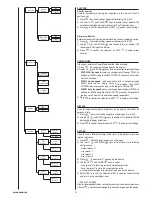
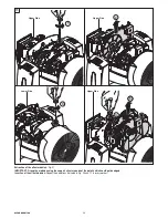
Functions of the buttons - Using the menu

Setting addresses and options with the projector disconnected
The projector’s DMX address, as well as other possible operating options, can also be set when the appliance is disconnected from the electricity supply.
All that is needed is to press

F

to momentarily activate the display and thus access the settings. Once the required operations have been carried out,

the display will switch off again after a wait time of 30 seconds.
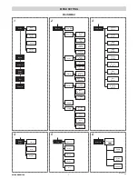
USING THE MENU: 

1) Press 

F

once – “Main Menu” appears on the display.
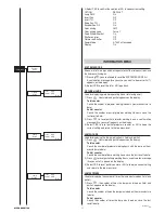
2) Use the UP 

B

and DOWN 

C

keys to select the menu to be used:

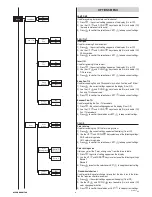
• Setup (Setup Menu): To set the setting options.
• Option (Option Menu): To set the operating options
• Informations (Informations Menu): To read the counters, software version and other  information.
• Manual Control (Manual control Menu): To trigger the test and manual control functions.
• Test (Test Menu): To check the proper functionning of  effects
• Advanced (Advanced Menu): Access to the "Advanced menu" is recommended for a trained technical personnel.
To enable the "Advanced" see pag.13

3) Press

F

to display the first item in the selected menu.
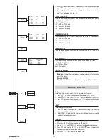
4) Use the UP 

B

and DOWN 

C

keys to select the MENU items.

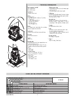
Confirms  the  displayed  value,  or  activates  the  displayed  function,  or  enters  the  successive
menu. 

Decreases the value displayed (with auto-repetitions) or passes to the next item in the menu.

Increases the value displayed (with auto-repetitions) or passes to the previous item in a menu.

Return to the top level

Commute from units, tens, hundreds, in the "Address", "Fixture ID" and "Calibration" menù. 

F
C

DOWN

B

UP

D

LEFT

E

RIGHT

Summary of Contents for ALPHA BEAM 700

Page 1: ...anual to ensure the fitting is installed used and serviced correctly and safely CLAY PAKY S p A disclaims all liability for damage to the fitting or to other property or persons deriving from installation use and maintenance that have not been carried out in conformity with this instruction manual which must always accompany the fitting CLAY PAKY S p A reserves the right to modify the characterist...

Page 2: ... must be carried out by a qualified electrical installer Check that the mains frequency and voltage correspond to those for which the projector is designed as given on the electrical data label This label also gives the input power to which you need to refer to evaluate the maximum number of fittings to connect to the electricity line in order to avoid overloading Temperature of the external surfa...

Page 3: ...4 5 4 5 3 ALPHA BEAM 700 UNPACKING AND PREPARATION Lamp 700W fitted into projector 099101 2 x 183102 802 1 90 9 0 9 0 9 0 LOCKED UNLOCKED PAN Mechanism Lock and Release every 90 Fig 2 TILT Mechanism Lock and Release every 45 Fig 3 2 3 Packing contents Fig 1 ...

Page 4: ...led on the floor resting on special rubber feet on a truss or on the ceiling or wall WARNING with the exception of when the projector is positioned on the floor the safety cable must be fitted Cod 105041 003 available on request This must be securely fixed to the support structure of the projector and then connected to the fixing point at the centre of the base ...

Page 5: ...status It should be noted than when this condition occurs any possible value that has been modified but not yet confirmed with the Fkey will be cancelled CONTROL PANEL 1 2 Dmx Address Warning Message Fixture ID 8 Continue Connecting to the control signal line DMX Fig 7 Use a cable conforming to specifications EIA RS 485 2 pole twisted shielded 120Ohm characteristic impedance 22 24 AWG low capacity...

Page 6: ...ss Fto momentarily activate the display and thus access the settings Once the required operations have been carried out the display will switch off again after a wait time of 30 seconds USING THE MENU 1 Press F once Main Menu appears on the display 2 Use the UP B and DOWN C keys to select the menu to be used Setup Setup Menu To set the setting options Option Option Menu To set the operating option...

Page 7: ...alibration Upload Firmware Setup Model Continue 5 Pan Tilt Colour Beam Gobo All Test Dmx Address Channel Mode Ethernet Interface Fixture ID Network params 2 Lamp Dmx Pan Tilt Color Display Option Invert Pan Invert Tilt Swap Pan Tilt Encoder Pan Tilt Color Mixing Fixed Wheel Shortcut Setting Default Preset User Preset 1 User Preset 2 User Preset 3 Shutter Shutter On Error Dimmer On Shutter Power Mo...

Page 8: ... to set Control Protocol It lets you select the Control Protocol Art net to assign according to the control unit used 1 Press Fthe current setting appears on the display 2 Use the UP Band DOWN Ckeys to select one of the following settings Disabled Art net on IP 2 Art net on IP 10 3 Press Fto confirm the selection or LEFT Dto keep the current setting Repeat on DMX It lets you enable the transmissio...

Page 9: ... F the current settings appear on the display On or Off 2 Use the UP B and DOWN C keys to enable On or disable Off Pan Tilt encoders 3 Press Fto confirm the selection or LEFT Dto keep current settings COLOR Color mixing Used for reversing the CMY color mixing system 1 Press F the current settings appear on the display On or Off 2 Use the UP Band DOWN Ckeys select one of the following settings RGB ...

Page 10: ...fans switch from Full speed to Low speed respectively 3 Press Fto confirm the selection or LEFT Dto keep current setting DISPLAY Used for automatically reduce brightness on the display after about 30 seconds in idle 1 Press F the current settings appear on the display On or Off 2 Use the UP Band DOWN Ckeys to enable On or disable Off the decreasing of display brightness 3 Press Fto confirm the sel...

Page 11: ...e number of projector working hours with the lamp on from manufacture to date Partial counter Counts the number of lamp working hours since the last reset to date 2 Press Fto reset partial lamp working hours a confirmation message Are you sure appears on the display 3 Select YES to reset partial counter or NO to keep the current setting and return to the top menu level LAMP STRIKES Used for displa...

Page 12: ...Ethernet Address 12 ALPHA BEAM 700 LAMP Used for turning lamp on and off from the projector control panel 1 Press F the current settings appear on the display On or Off 2 Use the UP Band DOWN Ckeys to turn the lamp on On or off Off 3 Press F to confirm the selection or LEFT D to keep current settings and return to the top level RESET Used for resetting the projector 1 Press F to reset the projecto...

Page 13: ...d DOWN Cbuttons to make the adjustment by setting a value between 0 and 255 4 Press F to confirm the selection or LEFT D to keep current set tings and return to the top level FACTORY DEFAULT Allows you to restore default values of all channels 128 1 Press F a confirmation message appears on the display Reset calibration to factory default 2 Select YES to reset calibration to factory default or NO ...

Page 14: ...ocking and releasing Pan and Tilt movements Refer to the instructions in the UNPACKING AND PREPARATION section Opening the head covers Fig 10 Closing the head covers Fig 11 2 1 1 4 Turn 1 2 1 4 Turn 3 4 10 11 MAINTENANCE ...

Page 15: ...ot touch the lamp s envelope with bare hands Should this happen clean the bulb with a cloth soaked in alcohol and dry it with a clean dry cloth IMPORTANT Make sure the lamp is inserted with the external contact A facing the elliptical reflector s slot Lamp regulation Fig 14 To centre the lamp turn the three adjusting screws as shown in the figure Opening and closing lamp compartment Fig 12 ...

Page 16: ... 001 085601 001 085909 001 085603 001 085801 001 085910 001 085802 001 085606 001 Upper Side 15 Replacing fixed gobos ø 31 5 mm max 25 mm image thickness max 1 1 mm Fig 15 WARNING Before using personalised gobos contact Clay Paky ...

Page 17: ...personalised gobos contact Clay Paky Bearing group replacement Fig 16 16 COATED GLASS GOBOS TYPE 1 COATED GLASS GOBOS TYPE 2 Grey Black side away from lamp Reflective side towards lamp Coated side towards lamp Uncoated side Coated side Uncoated side 18 To determine which side of a godo is coated hold an odject up to it On the uncoated side there is a space between the object and its reflection Gob...

Page 18: ...tors and filters It is recommended that the projector undergoes an annual service by a qualified technician for special maintenance involving at least the following operations General cleaning of internal parts Restoring lubrication of all parts subject to friction using lubricants specifically supplied by Clay Paky General visual check of the internal components cabling mechanical parts etc Elect...

Page 19: ...19 ALPHA BEAM 700 Lower Side 2 4 3 Upper Side 1 thermostat 20 Extraction of the effect modules Preliminary operations Fig 20 Continue ...

Page 20: ...1 IMPORTANT Grasp the modules using the support structure and not the details which could get damaged Insertion of the effect modules Repeat the operations indicated in Fig 20 and 21 in reverse order Lower Side 3 1 Upper Side 2 Upper Side 8 4 Upper Side 5 21 ...

Page 21: ...ntry of liquids CE Marking In conformity with the European Union Low Voltage Directive 2006 95 CE and Electromagnetic compa tibility Directive 2004 108 CE Safety Devices Bipolar circuit breaker with thermal protection Automatic break in power supply in case of overheating or failed operation of cooling system Cooling Forced ventilation with axial fans Body Aluminium structure with die cast plastic...

Page 22: ... FOCUS PAN PAN FINE TILT TILT FINE FUNCTION RESET LAMP CONTROL with Option Lamp Dmx ON 1 2 3 4 5 6 7 8 9 10 11 12 13 14 15 16 17 18 19 20 21 22 23 24 25 26 CYAN MAGENTA YELLOW COLOUR WHEEL STOP STROBE DIMMER DIMMER FINE IRIS STATIC GOBO CHANGE ROTATING GOBO CHANGE GOBO ROTATION PRISM INSERTION PRISM ROTATION FROST FOCUS PAN PAN FINE TILT TILT FINE FUNCTION RESET LAMP CONTROL with Option Lamp Dmx O...

Page 23: ...power when the channels level is put higher than 0 STOP STROBE channel 5 IMPORTANT The lamp dim to half power 1 second after the channel stay at 0 level The lamp goes back to full power when the channel level is put higher than 0 MACRO BIT EFFECT 252 255 98 7 100 OPEN 0 3 0 0 1 2 CLOSED 213 225 83 7 88 2 RANDOM SLOW STROBE 4 1 7 SLOW STROBE 1 flash sec 103 40 5 FAST STROBE 12 flash sec 104 107 41 ...

Page 24: ...AST SPEED GOBO 3 SHAKE SLOW SPEED GOBO 2 SHAKE FAST SPEED GOBO 2 SHAKE SLOW SPEED FAST ROTATION 100 rpm SLOW ROTATION 5 rpm STOP SLOW ROTATION 5 rpm FAST ROTATION 100 rpm GOBO 8 GOBO 7 GOBO 6 GOBO 5 GOBO 4 GOBO 3 GOBO 2 GOBO 1 WHITE BIT EFFECT 255 240 239 224 223 208 207 192 191 176 175 160 159 118 114 117 113 72 64 71 56 63 48 55 40 47 32 39 24 31 16 23 8 15 0 7 100 94 0 93 7 88 0 87 5 81 7 81 2 ...

Page 25: ...ion with option InvertPanGOn Tilt conventionally represented at 14 and option Invert TiltGOff BIT 255 100 0 0 0 BIT 255 100 0 0 0 PAN channel 16 Operation with option InvertPanGOff Tilt conventionally represented at 14 and option Invert TiltGOff TILT channel 18 Operation with option Invert TiltGOff Pan conventionally represented at 0 and option Invert PanGOff BIT 255 100 128 50 0 0 0 0 S E TX SEL ...

Page 26: ... 84 2 82 5 83 2 81 2 82 0 80 0 81 0 50 79 5 30 49 7 10 29 7 0 0 9 7 COMPLETE RESET Complete reset is activated passing throug the unused range and staying 5 seconds in complete reset levels Rotating Gobo OFFSET 13 Rotating Gobo OFFSET 12 Rotating Gobo OFFSET 11 Rotating Gobo OFFSET 10 Rotating Gobo OFFSET 9 Rotating Gobo OFFSET 8 Rotating Gobo OFFSET 7 Rotating Gobo OFFSET 6 Rotating Gobo OFFSET 5...

Page 27: ...88 89 25 90 91 26 92 93 94 27 95 96 28 97 98 99 29 100 101 102 30 103 104 31 105 106 107 32 108 109 33 110 111 112 34 113 114 35 115 116 117 36 118 119 37 120 121 122 38 123 124 125 39 126 127 40 128 BIT Seconds 129 130 41 131 132 42 133 134 135 43 136 137 44 138 139 140 45 141 142 46 143 144 145 47 146 147 48 148 149 150 49 151 152 153 50 154 155 51 156 157 158 52 159 160 53 161 162 163 54 164 16...

Page 28: ...CLAY PAKY S p A Via Pastrengo 3 b 24068 Seriate BG Italy Tel 39 035 654311 Fax 39 035 301876 www claypaky it Rev 2 02 11 Cod 099101 EN www gfstudio com ...

Reviews: