background image

• Preparing the warning label

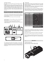
Find the warning label (19) on the re-lamping cover (18) and, if necessary, replace it
with one of the optional multilingual labels (16) located in the projector lamp
compartment. For the instructions on opening the projector, read paragraph 
4 MAINTENANCE.

CAUTION: Read carefully and meticulously apply the information and
instructions given on this label. In addition, check it is never removed as it
contains important safety information.

• Fitting the lamp

Refer to the instructions for opening the projector and changing the lamp in
paragraph 4 MAINTENANCE.

2

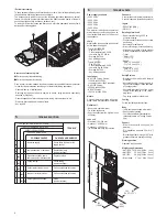
• Packing contents

Besides the projector, the packing also contains the following accessories:

- This instructions manual 

code 099406 (1).

- 2 spacers code

167002/001 (2).

- 1 right bracket support plate

code 167003/001 (3).

- 1 left bracket support plate

code 167003/002 (4).

- 2 eyebolts M8x20mm 

code 167004/001 (5).

- 2 nuts M8 

code 020106/006 (6).

- 2 knobs code 020502 (7).

- 2 plane washers ø10,5mm

code 020210/004 (8).

- 1 bracket 

code 101011/001 (9).

- 4 bracket bushings 

code 101014/001 (10).

- 4 countersunk washers 

code 080606/001 (11).

- 4 countersunk head

screws M8x20mm 
code 020005/001 (12).

- 1 Allen wrench 5 mm 

code 050001 (13).

- 4 handles 

code 082017/001 (14)
(only for TV version).

- 8 screws TCEI M8x20 

code 020002/029 (15).

- Multilingual label (16) with 

safety information code 081948/003 
(located in the projector lampholder compartment).

- 1 safety ropes code 105041/001 (17).

• Fitting the bracket  

• Fitting the handles (only for TV version)

2

13

14

15

12

1

4

3

5

6

7

8

9

10

11

17

16

7

6

2

4

5

8

3

12

11

9

10

13

15

14

4

19

18

UNPACKING AND PREPARING

2

• Unpacking

Open the box from the top, take all the accessories out of the box and remove the
polystyrene containing structures.
Open the plastic bag, remove the projector from the box frame and position it on a
horizontal top where access is easy to carry out the following preliminary work.

Summary of Contents for HMI 575

Page 1: ... protect the supply lines of the projectors from indirect contact and or shorting to earth by using appropriately sized residual current devices Connecting to the supply mains Connection to the electricity mains must be carried out by a qualified electrical installer Check that the mains frequency and voltage correspond to the frequency and voltage stated on the electrical data label for which the...

Page 2: ...03 002 4 2 eyebolts M8x20mm code 167004 001 5 2 nuts M8 code 020106 006 6 2 knobs code 020502 7 2 plane washers ø10 5mm code 020210 004 8 1 bracket code 101011 001 9 4 bracket bushings code 101014 001 10 4 countersunk washers code 080606 001 11 4 countersunk head screws M8x20mm code 020005 001 12 1 Allen wrench 5 mm code 050001 13 4 handles code 082017 001 14 only for TV version 8 screws TCEI M8x2...

Page 3: ...and control unit and between different projectors must be made with a cable conforming to the EIA RS 485 specifications bipolar braided shielded 120Ω characteristic impedance 22 24 AWG low capacity IMPORTANT Do not use microphone cable or any other cable whose specifications are different to the ones stated above The terminations need to be made with male female connectors type XLR with 5 pins If ...

Page 4: ...nnels 37 42 Projector 9 Channels 49 54 Projector 10 Channels 55 60 Projector 8 Channels 43 48 DIGITAL START ADDRESS SELECT OPTION SELECT DIGITAL INPUT LEDS 1 4 8 1 2 4 8 16 128 32 64 TEST 256 ON 1 2 4 3 6 5 7 8 10 9 DIGITAL INPUT 1 2 4 3 6 5 The above information can also be displayed by carrying out at least one of the following operations Setting all the DIL Dual In Line switches of the addresse...

Page 5: ...eeds to be positioned with the protrusion 31 visible on the bulb outside the optical axis of the projector For this purpose it is recommended to turn the protrusion towards the top cover 18 27 24 32 25 34 34 33 Replacing colour filters Find the filter to be replaced grip it between your fingers and push it towards the movable point of anchorage 33 until the filter comes out of the fixed points of ...

Page 6: ...0µF standard HMI 1200 Version 3000VA at 220V 50Hz HMI 575 Version 1500 VA at 220V 50Hz Motors 9 stepper motors operating with micro steps totally microprocessor controlled Optical unit Base in die cast aluminium Twin lens condenser Spherical reflector with a high luminous efficiency Lens unit Standard 1 2 5 250 mm Optional 1 3 3 300 mm Optional 1 1 6 160 mm to be fitted internally of projector HMI...

Page 7: ...12 GOLDEN SCAN 3 HMI 575 HMI 1200 HMI 1200 TV ACCESSORI OPZIONALI OPTIONAL ACCESSORIES ACCESSOIRES OPTIONNELS OPTIONALE ZUBEHÖRTEILE ACCESORIOS OPCIONALES C21061 C21029 C21030 ...

Reviews: