background image

29

1

2

4

5

6

9

8

7

10

11

3

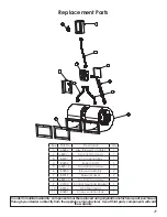
Key Part No.

Description

Qty

1

68234

Assy, Blower/T’stat Brkt.

1

2

68231-1

Fan Cntrl Cord Assy

1

3

80131

4 X 4 Junction Box

1

4

80232

Supply Cord

1

5

68231-2

Fan Cntrl Cord Assy

1

6

80230

Blower Assembly

2

7

89319

Blower Gasket

2

8

68231-3

Fan Cntrl Cord Assy

1

9

22140

Control Mounting Bracket

1

10

80314

F120 Thermodisc

1

11

80231

Cover, Junction Box

1

In order to maintain warranty, components must be replaced using original manufacturers parts purchased 

through your dealer or directly from the appliance manufacturer.  Use of third party components will void 

the warranty.

Replacement Parts

Summary of Contents for CF700M

Page 1: ...on and Operation Manual Model CF700M Installation is to be preformed by a qualified installer SAVE THESE INSTRUCTIONS This unit is certified UL 391 United States Stove Company 227 Industrial Park Rd South Pittsburg TN 37380 852511 0804F U S ENVIRONMENTAL PROTECTION AGENCY Certified to comply with the 2016 particulate emission standards Not approved for sale after May 15 2020 ...

Page 2: ... central furnace overheating and causing the central furnace to operate other than as intended Power source not controlled by furnace main disconnect Respect all local and national codes when installing this unit This unit is not to be connected to a chimney flue serving another appliance This unit is designed to burn solid hardwood only 40 73 38 39 26 07 1 97 33 63 28 01 40 73 38 39 26 07 ...

Page 3: ...shown to deliver heat at a rate of 20 568 64 166 BTU hr This heater achieved a particulate emissions rate of 0 408 lb mmBtu when tested to method CSA B415 1 10 and an overall efficiency of 70 8 The maximum overall heat output of this heater was tested to be 108 758 Btu hr This wood heater has a manufacturer set minimum low burn rate that must not be altered It is against federal regulations to alt...

Page 4: ...nd chimney must be kept in good condition These instructions also apply to a draft inducer if used To prevent flame or smoke spillage the slide baffle must be pulled out and the fuel loading door left cracked for 10 seconds prior to opening door fully Load fuel carefully or damage may result Hot while in operation Keep children clothing and furniture away Contact may cause skin burns Do not use ch...

Page 5: ...k arrangement TOOLS AND MATERIALS NEEDED FOR INSTALLATION The following is a list of tools and materials needed to install your furnace 7 16 socket wrench 5 16 socket Best if using a power drill and a socket bit Pair of pliers or channel locks Power drill with an 1 8 drill bit to install sheet metal screws into connector pipe Sheet metal screws Non combustible floor protector as specified in this ...

Page 6: ...ld not be allowed to create negative pressure in the room where the furnace is installed LOCATING YOUR FURNACE INSURE THAT THE REQUIRED MAINTENANCE CLEARANCES ARE MAINTAINED Your furnace must be installed as shown in this manual and in compliance with all local and national codes It is of the utmost importance that the clearances to combustible materials be strictly adhered to during installation ...

Page 7: ...nce Clearance Left 24 610 K Maintenance Clearance Right 24 610 L Maintenance Clearance Rear 36 915 P M Q N R R Back wall Arrière Mur Side wall Paroi Latérale B A J K L H MAINTENANCE CLEARANCE Dimension Inch mm M Front 22 558 8 N Flue rear 2 51 P Left 8 204 Q Right 8 204 R Flue Side 2 51 FLOOR PROTECTOR REQUIREMENTS FLOOR PROTECTOR The furnace must be placed on solid concrete solid masonry or when ...

Page 8: ...e plenums installed to the furnace shall be constructed of metal in accordance with NFPA 90B 2 1 3 When installing this furnace the hot air plenum is to have a minimum height of 24 610mm if the top of the first vertical section is not flush with the top of the first horizontal section of ductwork If the top of the plenum is flush with the top of the first horizontal section of ductwork then the mi...

Page 9: ... listed below The return air will duct directly to the return of the new furnace and not be pulling through any other furnace The output of the existing furnace must be equal to or greater than this wood furnace If installing in a parallel configuration the ductwork may need adjustments so as to maintain the static pressure between 0 2 W C And 0 05 W C A back flow damper must be installed in the s...

Page 10: ...10 CENTRAL INSTALLATION ADD ON INSTALLATION ...

Page 11: ... COLD AIR RETURN SOLID FUEL FURNACE FILTER BOX EXISTING FURNACE COLD AIR RETURN WARM AIR TO EXISTING DUCT WORK INSTALLATION B N C SOLID FUEL FURNACE FILTER BOX COLD AIR RETURN EXISTING FURNACE PLENUM COLLECTOR BOX WARM AIR TO EXISTING DUCT WORK TO EXISTING ...

Page 12: ...12 INSTALLATION D INSTALLATION E ...

Page 13: ...13 INSTALLATION H TOP VIEW FRONT VIEW INSTALLATION F INSTALLATION G ...

Page 14: ... of furnace cabinet with the two screws provided Mount the conduit assembly from the junction box to the thermostat bracket Crimp the two female terminals to each of the wire leads Plug the wires to the thermodisc NOTE It does not matter which of the two wires plugs to which terminal on the thermodisc 3 Remove blowers from cartons Remove junction box cover Attach clip nuts as in figure shown Insta...

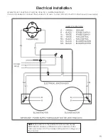
Page 15: ...cian It is recommended to connect the furnace to its own 15 amp 120 Volt circuit from the house power supply 105 C NOTE Wire leads from the distribution blower are usually BOTH BLACK Makes no difference which leads from the motor s connects to the corresponding leads coming out of the conduit ...

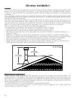
Page 16: ...hould be double or triple wall pipe to ensure proper draft The chimney must exceed any part of the building or other obstruction within a 10 3 04m distance by a height of 2 0 6m Installation of an interior chimney is always preferable to an exterior chimney The interior chimney will be hotter than an exterior chimney that is being cooled by the ambient air outside the house Therefore the gas which...

Page 17: ... a professional Make sure there are no cracks loose mortar or other signs of deterioration and blockage Have the chimney cleaned before the furnace is installed and operated When connecting the furnace through a combustible wall to a masonry chimney special methods are needed as explained in the Combustible Wall Chimney Connector Pass Throughs Section ...

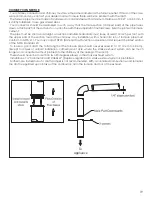
Page 18: ...ector and a minimum 24 gauge ventilated wall thimble which has two air channels of 1 25 4 mm each construct a wall pass through There shall be a minimum 6 152 4 mm separation area containing fiberglass insulation from the outer surface of the wall thimble to wall combustibles Support the wall thimble and cover its opening with a 24 gauge minimum sheet metal support Maintain the 6 152 4 mm space Th...

Page 19: ...upper end of the section toward the chimney Any installation with a horizontal run of furnace pipe must conform to NFPA 211 You may contact NFPA National Fire Protection Association and request the latest edition of the NFPA Standard 211 To insure a good draft the total length of the furnace pipe should never exceed 8 to 10 2 4m to 3 04 m Except for cases of vertical installation cathedral roof st...

Page 20: ...same manufacturer and install the ceiling support package or wall pass through and T section package firestops where needed insulation shield roof flashing chimney cap etc Maintain proper clearance to the structure as recommended by the manufacturer The chimney must be the required height above the roof or other obstructions for safety and proper draft operation ...

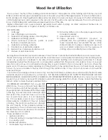
Page 21: ... or covered area from rain or snow also accelerates drying time A good indicator if wood is ready to burn is to check the piece ends If there are cracks radiating in all directions from the center then the wood should be dry enough to burn If your wood sizzles in the fire even though the surface is dry it may not be fully cured and should be seasoned longer Your furnace was designed to burn wood o...

Page 22: ...r 4 first fires Never start your furnace outside You will not be able to see if you are over heating LIGHTING YOUR WOOD FURNACE 1 Make sure that your furnace has been installed as per the instructions outlined in this manual and the proper power is supplied to it 2 Open the fuel loading door 3 Note If there already is a bed of hot glowing coals in the combustion chamber proceed directly to the Pre...

Page 23: ...l indicate the temperature of your gas exhaust fumes within the smoke exhaust system The ideal temperature for these gases is somewhere between 275 F and 500 F Below these temperatures the build up of creosote is promoted Above 500 degrees heat is wasted since a too large quantity is lost into the atmosphere TO PREVENT CREOSOTE BUILD UP Always burn dry wood This allows clean burns and higher chimn...

Page 24: ...ce and burn well seasoned wood Higher burn rates are not always the best heating burn rates after a good fire is established a lower burn rate may be a better option for efficient heating A lower burn rate slows the flow of usable heat out of the home through the chimney and it also consumes less wood SMOKE AND CO MONITORS Burning wood naturally produces smoke and carbon monoxide CO emissions CO i...

Page 25: ...ol over the combustion maximum efficiency and security To change the door gasket simply remove the damaged one Carefully clean the available gasket groove apply a high temperature silicone sold for this purpose and install the new gasket You may light up your furnace again approximately 24 hours after having completed this operation This unit s feed door uses a 3 4 diameter rope gasket This unit s...

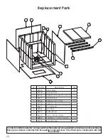
Page 26: ...l void the warranty Key Part No Description Qty 1 27312G Side Panel 2 2 891214 Stub Collar 8 2 3 27322 Top Panel 1 4 27329 Cabinet Back 1 5 26761 Hearth Plate 1 6 26765 Air Wash Plate 1 7 27325 Air Divider 2 8 88057 Ash Pan Door Thermocord 1 2 20 Key Part No Description Qty 9 40627 Heat Exchange Door 1 10 892351 Exchange Handle 1 11 27327 Air Damper 1 12 26866 Door Latch 1 13 892503 Damper Handle ...

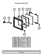
Page 27: ...ance manufacturer Use of third party components will void the warranty 1 2 3 4 5 6 7 8 9 Key Part No Description Qty 1 891135 Handle Spring Lg Nickel 1 2 892347 Door Handle 1 3 40603 Cast Door 1 4 88082 Thermocord 3 4 50 5 88087 Glass Gasket 1 X 1 8 1 6 892346 Door Glass 1 7 26848 Window Clamp 1 8 26856 Door Cover Plate 1 Replacement Parts ...

Page 28: ...brick Half 4 1 2 X 4 1 2 1 7 88212 Base Blanket 1 8 40561 Ash Plug 1 9 88210 Baffle Board 2 10 86757 Tube Air Secondary 4 11 83874 1 8 Dia X 1 1 2 Cotter Pin 4 12 26945 Brick Retainer 1 Replacement Parts Inordertomaintainwarranty componentsmustbereplacedusingoriginalmanufacturerspartspurchased through your dealer or directly from the appliance manufacturer Use of third party components will void t...

Page 29: ... 1 6 80230 Blower Assembly 2 7 89319 Blower Gasket 2 8 68231 3 Fan Cntrl Cord Assy 1 9 22140 Control Mounting Bracket 1 10 80314 F120 Thermodisc 1 11 80231 Cover Junction Box 1 Inordertomaintainwarranty componentsmustbereplacedusingoriginalmanufacturerspartspurchased through your dealer or directly from the appliance manufacturer Use of third party components will void the warranty Replacement Par...

Page 30: ... costs LIMITATIONS AND EXCLUSIONS 1 United States Stove Company shall not be liable for incidental consequential special or contingent damages anyone might suffer as a result of their breach of this written warranty or any implied warranty 2 Should the heater be replaced by United States Stove Company free of charge all further warranty obligations are thereby met 3 Parts and or service replacemen...

Page 31: ..._____________ Company ________________________________________ Telephone No ______________________________________ Stove Inspected Chimney Swept Items Replaced ____________________________________ Service 05 Date ________________________ Engineer Name _____________________________________ Company __________________________________________ Telephone No ______________________________________ Stove I...

Page 32: ...mber which is on the nameplate attached to the stove When ordering repair parts always give the following information as shown in this list 1 The part number ________________________________ 2 The part description _____________________________ 3 The model number ______________________________ 4 The serial number ________________________________ United States Stove Company 227 Industrial Park Road ...

Reviews: