Sect02_CSMG_b.fm
2-2
04/19/2019
Steam Master Instruction Manual
2.2.3.1 Main Temperature Limit Controller
(MTLC2)
This over-temperature safety controller (see
Fig. 2-2) has a fixed trip-point
1
. It will interrupt the
motor and burner control circuits on a severe over-
temperature condition.
It must be manually reset
before normal operation can be resumed. This is
done through 010.
A “STEAM COIL TEMP. -
OVER LIMIT-” safety shutdown condition will be
indicated on the OIU, and an audible alarm will
sound.
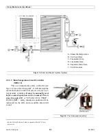
Fig. 2-1.
Water and Steam System (typical)
OPTIONAL ECONOMIZER
A
B
C
D
E
A– Steam Discharge Valve
B– Coil Feed Valve
C– Feedwater Pump
D– Feedwater Valve
E– Separator Drain Valve
F– Coil Drain Valve
F
1
See the Table of Reference Values in Appendix B for MTLC trip-
point value.
Fig. 2-2.
Thermocouple Assembly
Summary of Contents for Steam Master CSMG-15
Page 1: ...STEAM MASTER SERIES USER MANUAL Cover CSMG 15 30 40 R027880B 20190603 ...
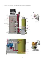
Page 8: ...vi The controls and features may differ depending on the unit s size and specifications ...
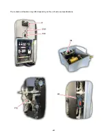
Page 9: ...vii The controls and features may differ depending on the unit s size and specifications ...
Page 14: ...Specifications_CSM_a fm xii 11 22 2018 This page intentionally left blank ...
Page 44: ...Sect05_CSMG_a fm 5 6 11 26 2018 Steam Master Instruction Manual NOTES ...
Page 68: ...HeatingSect_SM15_a fm A 2 04 30 2019 Fig 01A Main Heating Section SM15 ...
Page 69: ...04 30 2019 A 3 HeatingSect_SM15_a fm FIG 01A Main Heating Section SM15 ...
Page 70: ...HeatingSect_SM15_a fm A 4 04 30 2019 Fig 01B Economizer Stack Outlet Kit SM15 ...
Page 71: ...04 30 2019 A 5 HeatingSect_SM15_a fm FIG 01B Economizer Stack Outlet Kit SM15 ...
Page 72: ...HeatingSect_SM30_b fm A 6 12 05 2018 Fig 01C Main Heating Section SM30 ...
Page 73: ...12 05 2018 A 7 HeatingSect_SM30_b fm FIG 01C Main Heating Section SM30 ...
Page 74: ...HeatingSect_SM30_b fm A 8 12 05 2018 Fig 01D Economizer Coil SM30 ...
Page 75: ...12 05 2018 A 9 HeatingSect_SM30_b fm FIG 01D Economizer Coil SM30 ...
Page 76: ...HeatingSect_SM45_b fm A 10 04 30 2019 Fig 01C Main Heating Section SM40 ...
Page 77: ...04 30 2019 A 11 HeatingSect_SM45_b fm FIG 01C Main Heating Section SM40 ...
Page 78: ...HeatingSect_SM45_b fm A 12 04 30 2019 Fig 01D Economizer Coil SM40 Sht 1 of 2 ...
Page 79: ...04 30 2019 A 13 HeatingSect_SM45_b fm FIG 01D Economizer Coil SM40 ...
Page 86: ...Sep Trap PressMfld_SM153040_b fm A 20 04 30 2019 Fig 02E Pressure Indicating System ...
Page 87: ...04 30 2019 A 21 Sep Trap PressMfld_SM153040_b fm FIG 02E Pressure Indicating System ...
Page 90: ...PumpHkup C1 C2_parts_a fm A 24 03 05 2019 Fig 05A Pump Assy C1 ...
Page 91: ...03 05 2019 A 25 PumpHkup C1 C2_parts_a fm FIG 05A Pump Assy C1 ...
Page 92: ...03 05 2019 A 26 PumpHkup C1 C2_parts_a fm Fig 05B Pump Assy C2 ...
Page 93: ...PumpHkup C1 C2_parts_a fm A 27 03 05 2019 FIG 05B Pump Assy C2 ...
Page 98: ...Blank_Left fm A 32 08 16 2017 This page intentionally left blank ...
Page 106: ...R027906A 2018 10 22 ...
Page 107: ...NOTES ...
Page 108: ...Steam Generator Instruction Manual This page intentionally left blank ...
Page 109: ......

