Sect07_CSMG_b.fm
7-2
04/26/2019
Steam Master Instruction Manual
7.2
Feedwater Pump Maintenance
Avoid bodily injury. Always lock-out main
electrical power to the machine to prevent
accidental machine startup when repairing or
performing maintenance on the machine.
7.2.1
Check-Valve Maintenance
(See Fig. 7-3.)
a. Unscrew check-valve caps (3) from
check-valve housings and disassemble
discs (6) and springs (2 and 5) from caps.
Remove scale and pits from discs by rub-
bing them in a “figure 8” motion on a
piece of fine sandpaper (wet-or-dry no.
400 or finer) placed on plate glass. Discs
must be perfectly smooth and flat for
proper water pump operation.
Remove and process check-valves one
at a time to avoid interchanging parts.
b. Inspect springs (2 and 5) for distortion and
for free length. Free length of discharge
springs (5) should be 3/4 inch; free length
of intake springs (2) should be 1/2 inch.
Replace broken or distorted springs.
c. Damaged seats (1) may be removed with a
screw extractor (E-Z Out). Turn extractor
while lifting firmly until seat is removed.
Drive replacement seats in place with a
special seat driving tool (part no. UH-
18389) to avoid damage to the seat face.
7.2.2
Replacing Check-Valve Seats
To replace valve seats, use a special seat
puller (Part No. UH-25257) and a special seat driver
(Part No. UH-18389). A screw extractor (E-Z Out)
may also be used when removing seats. Proceed as
follows:
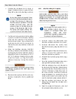
a. Adjust puller stem counterclockwise until
retracted catch extends below valve seat
when puller is inserted into check-valve
housing (Inset A, Fig. 7-4).
b. Extend catch and turn stem clockwise in
body until catch meets the bottom of the
valve seat (Inset B, Fig. 7-4)
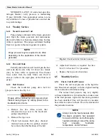
Fig. 7-3.
Pump Check-valve Maintenance
1. Check-valve Seat
2. Intake Spring
3. Check-valve Cap
4. Gasket
5. Discharge Spring
6. Check-valve Disc
PUMP ASSEMBLY
INTAKE/DISCHARGE
CHECK-VALVE
FEEDWATER
DISCHARGE
CHECK-VALVE
Summary of Contents for Steam Master CSMG-15
Page 1: ...STEAM MASTER SERIES USER MANUAL Cover CSMG 15 30 40 R027880B 20190603 ...
Page 8: ...vi The controls and features may differ depending on the unit s size and specifications ...
Page 9: ...vii The controls and features may differ depending on the unit s size and specifications ...
Page 14: ...Specifications_CSM_a fm xii 11 22 2018 This page intentionally left blank ...
Page 44: ...Sect05_CSMG_a fm 5 6 11 26 2018 Steam Master Instruction Manual NOTES ...
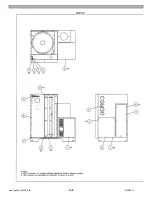
Page 68: ...HeatingSect_SM15_a fm A 2 04 30 2019 Fig 01A Main Heating Section SM15 ...
Page 69: ...04 30 2019 A 3 HeatingSect_SM15_a fm FIG 01A Main Heating Section SM15 ...
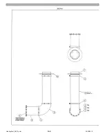
Page 70: ...HeatingSect_SM15_a fm A 4 04 30 2019 Fig 01B Economizer Stack Outlet Kit SM15 ...
Page 71: ...04 30 2019 A 5 HeatingSect_SM15_a fm FIG 01B Economizer Stack Outlet Kit SM15 ...
Page 72: ...HeatingSect_SM30_b fm A 6 12 05 2018 Fig 01C Main Heating Section SM30 ...
Page 73: ...12 05 2018 A 7 HeatingSect_SM30_b fm FIG 01C Main Heating Section SM30 ...
Page 74: ...HeatingSect_SM30_b fm A 8 12 05 2018 Fig 01D Economizer Coil SM30 ...
Page 75: ...12 05 2018 A 9 HeatingSect_SM30_b fm FIG 01D Economizer Coil SM30 ...
Page 76: ...HeatingSect_SM45_b fm A 10 04 30 2019 Fig 01C Main Heating Section SM40 ...
Page 77: ...04 30 2019 A 11 HeatingSect_SM45_b fm FIG 01C Main Heating Section SM40 ...
Page 78: ...HeatingSect_SM45_b fm A 12 04 30 2019 Fig 01D Economizer Coil SM40 Sht 1 of 2 ...
Page 79: ...04 30 2019 A 13 HeatingSect_SM45_b fm FIG 01D Economizer Coil SM40 ...
Page 86: ...Sep Trap PressMfld_SM153040_b fm A 20 04 30 2019 Fig 02E Pressure Indicating System ...
Page 87: ...04 30 2019 A 21 Sep Trap PressMfld_SM153040_b fm FIG 02E Pressure Indicating System ...
Page 90: ...PumpHkup C1 C2_parts_a fm A 24 03 05 2019 Fig 05A Pump Assy C1 ...
Page 91: ...03 05 2019 A 25 PumpHkup C1 C2_parts_a fm FIG 05A Pump Assy C1 ...
Page 92: ...03 05 2019 A 26 PumpHkup C1 C2_parts_a fm Fig 05B Pump Assy C2 ...
Page 93: ...PumpHkup C1 C2_parts_a fm A 27 03 05 2019 FIG 05B Pump Assy C2 ...
Page 98: ...Blank_Left fm A 32 08 16 2017 This page intentionally left blank ...
Page 106: ...R027906A 2018 10 22 ...
Page 107: ...NOTES ...
Page 108: ...Steam Generator Instruction Manual This page intentionally left blank ...
Page 109: ......


