04/26/2019
7-7
Sect07_CSMG_b.fm
Section VII–Component Maintenance
7.3
Feedwater Pump Relief Valve
Excessive leakage from the relief valve will
result in insufficient water to the heating coil and
will result in overheating. The relief valve (Fig. 7-8)
is factory preset for the following pumps:
• C2 pump .................... 275 psi
7.3.1
Adjustment
Under certain conditions, when starting
the machine, the feed pressure may
surge sufficiently to cause the relief
valve to release a small amount of
water. The feed pressure will return to
normal, however, after the machine
heats and the system becomes
stabilized.
a. Start the machine in the FILL position and
slowly close the coil feed valve until the
relief valve begins to discharge. When the
discharge begins, check the pressure on
the feed pressure gauge.
b. To raise the pressure adjustment, turn the
adjusting screw clockwise. Similarly, to
lower the pressure adjustment, turn the
adjusting screw counterclockwise. Secure
the adjusting screw with the lock nut after
adjustment process.
It is best to make these pressure
adjustments while the feedwater pump
is off. A feedwater pump that is running
places more resistance against the
adjusting nut.
c. Fully open the coil feed valve. Regularly
inspect the relief valve for leakage during
normal operation.
7.4
Temperature Controllers (MTLC1,
MTLC2)
The MTLCs are installed in the electrical
control box.
7.4.1
Check Main Temperature Limit
Controllers
a. Remove one thermocouple lead wire from
the MTLC. See Fig. 7-9 below.
b. Verify that a shutdown occurs and an
alarm is initiated within one minute.
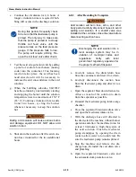
Fig. 7-8.
Feedwater Pump Relief Valves
Fig. 7-9.
Test MTLCs in electrical control box.
Summary of Contents for Steam Master CSMG-15
Page 1: ...STEAM MASTER SERIES USER MANUAL Cover CSMG 15 30 40 R027880B 20190603 ...
Page 8: ...vi The controls and features may differ depending on the unit s size and specifications ...
Page 9: ...vii The controls and features may differ depending on the unit s size and specifications ...
Page 14: ...Specifications_CSM_a fm xii 11 22 2018 This page intentionally left blank ...
Page 44: ...Sect05_CSMG_a fm 5 6 11 26 2018 Steam Master Instruction Manual NOTES ...
Page 68: ...HeatingSect_SM15_a fm A 2 04 30 2019 Fig 01A Main Heating Section SM15 ...
Page 69: ...04 30 2019 A 3 HeatingSect_SM15_a fm FIG 01A Main Heating Section SM15 ...
Page 70: ...HeatingSect_SM15_a fm A 4 04 30 2019 Fig 01B Economizer Stack Outlet Kit SM15 ...
Page 71: ...04 30 2019 A 5 HeatingSect_SM15_a fm FIG 01B Economizer Stack Outlet Kit SM15 ...
Page 72: ...HeatingSect_SM30_b fm A 6 12 05 2018 Fig 01C Main Heating Section SM30 ...
Page 73: ...12 05 2018 A 7 HeatingSect_SM30_b fm FIG 01C Main Heating Section SM30 ...
Page 74: ...HeatingSect_SM30_b fm A 8 12 05 2018 Fig 01D Economizer Coil SM30 ...
Page 75: ...12 05 2018 A 9 HeatingSect_SM30_b fm FIG 01D Economizer Coil SM30 ...
Page 76: ...HeatingSect_SM45_b fm A 10 04 30 2019 Fig 01C Main Heating Section SM40 ...
Page 77: ...04 30 2019 A 11 HeatingSect_SM45_b fm FIG 01C Main Heating Section SM40 ...
Page 78: ...HeatingSect_SM45_b fm A 12 04 30 2019 Fig 01D Economizer Coil SM40 Sht 1 of 2 ...
Page 79: ...04 30 2019 A 13 HeatingSect_SM45_b fm FIG 01D Economizer Coil SM40 ...
Page 86: ...Sep Trap PressMfld_SM153040_b fm A 20 04 30 2019 Fig 02E Pressure Indicating System ...
Page 87: ...04 30 2019 A 21 Sep Trap PressMfld_SM153040_b fm FIG 02E Pressure Indicating System ...
Page 90: ...PumpHkup C1 C2_parts_a fm A 24 03 05 2019 Fig 05A Pump Assy C1 ...
Page 91: ...03 05 2019 A 25 PumpHkup C1 C2_parts_a fm FIG 05A Pump Assy C1 ...
Page 92: ...03 05 2019 A 26 PumpHkup C1 C2_parts_a fm Fig 05B Pump Assy C2 ...
Page 93: ...PumpHkup C1 C2_parts_a fm A 27 03 05 2019 FIG 05B Pump Assy C2 ...
Page 98: ...Blank_Left fm A 32 08 16 2017 This page intentionally left blank ...
Page 106: ...R027906A 2018 10 22 ...
Page 107: ...NOTES ...
Page 108: ...Steam Generator Instruction Manual This page intentionally left blank ...
Page 109: ......


