Sect07_CSMG_b.fm
7-8
04/26/2019
Steam Master Instruction Manual
c. Replace the thermocouple lead wire.
d. Repeat steps a, b, and c for the other
MTLC.
If any of the MTLCs are suspected of
being faulty, remove it and conduct
further bench testing. Replace the
MTLC if it is faulty.
7.5
Operating Pressure Switch (OPS)
Adjustment
The OPS can be adjusted to open and stop
the burner at any desired maximum steam pressure
within the operating range of the switch and in
accordance with Clayton prescribed switch setpoint
parameters. The switch has a fixed differential and
will close and restart the burner when steam pres-
sure drops about 8 psi (0.55 bar) below the OPS
setpoint.
To adjust, turn the large slotted screw at the
top of the switch until the dial pointer on the switch
is opposite the maximum desired operating pres-
sure. The dial setting is approximate and final
adjustment should be made (if necessary) by reset-
ting the switch to shut off the burner when desired
maximum pressure is reached on the operating pres-
sure gauge.
7.6
Limit Pressure Switch (LPS)
Adjustment
The LPS is part of the motor circuit. In the
event of excessive steam discharge pressure, this
switch will actuate and shut down the machine
(interrupting the holding circuit). A manual reset is
required before the machine can be restarted.
7.6.1
Adjustment
To set the switch (using scale on switches)
manually increase the OPS and LPS setpoints to
some value above the desired LPS setting (a pres-
sure that is about halfway between the original OPS
setpoint and the opening pressure of the steam
safety relief valve(s)). Operate the machine and
slowly throttle the steam discharge valve to increase
the steam pressure to desired LPS setpoint. Set the
limit pressure switch (dial down) to open (shutting
machine off). Reset the OPS to its original setting
(See paragraph 7.5.).
7.7
Gas Pressure Switches
Damage to burner unit and steam generator will
result from improperly adjusted gas pressure
switches.
Maintenance and repair of the
packaged burner system and its
ancillary devices should ONLY be
performed by Clayton Service or by
Clayton-authorized service technicians.
A set of gas pressure switches, two GPSLs
and a GPSH, are part of the fuel system (See Fig.
7-10.). These switches will initiate a safety shut-
down when gas pressure falls out of range of the
switch’s setpoint.
The low gas pressure switch (GPSL)
closes
on an excessive drop in supply gas pressure; the
high gas pressure switch (GPSH)
opens
on an
excessive rise in burner pressure. If supply gas or
burner pressure exceeds the setpoint of the respec-
tive switch, the burner circuit will open and cause a
complete shutdown of the machine. A manual reset
is required if either switch is actuated.
A manual reset is required on the GPSL
installed at the main gas supply inlet. A manual
reset is required on the GPSH. The GPSH is found
inside the housing of the packaged burner unit.
Note
: Manual reset can be accomplished
without removing the clear cover. To manually
reset the pressure switch, press the spot on the cover
immediately above the red manual reset button
(Fig. 7-10).
If needed, the GPSL/GPSH setpoint may be
adjusted as follows:
Summary of Contents for Steam Master CSMG-15
Page 1: ...STEAM MASTER SERIES USER MANUAL Cover CSMG 15 30 40 R027880B 20190603 ...
Page 8: ...vi The controls and features may differ depending on the unit s size and specifications ...
Page 9: ...vii The controls and features may differ depending on the unit s size and specifications ...
Page 14: ...Specifications_CSM_a fm xii 11 22 2018 This page intentionally left blank ...
Page 44: ...Sect05_CSMG_a fm 5 6 11 26 2018 Steam Master Instruction Manual NOTES ...
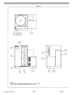
Page 68: ...HeatingSect_SM15_a fm A 2 04 30 2019 Fig 01A Main Heating Section SM15 ...
Page 69: ...04 30 2019 A 3 HeatingSect_SM15_a fm FIG 01A Main Heating Section SM15 ...
Page 70: ...HeatingSect_SM15_a fm A 4 04 30 2019 Fig 01B Economizer Stack Outlet Kit SM15 ...
Page 71: ...04 30 2019 A 5 HeatingSect_SM15_a fm FIG 01B Economizer Stack Outlet Kit SM15 ...
Page 72: ...HeatingSect_SM30_b fm A 6 12 05 2018 Fig 01C Main Heating Section SM30 ...
Page 73: ...12 05 2018 A 7 HeatingSect_SM30_b fm FIG 01C Main Heating Section SM30 ...
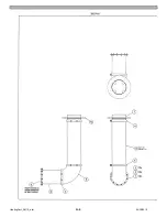
Page 74: ...HeatingSect_SM30_b fm A 8 12 05 2018 Fig 01D Economizer Coil SM30 ...
Page 75: ...12 05 2018 A 9 HeatingSect_SM30_b fm FIG 01D Economizer Coil SM30 ...
Page 76: ...HeatingSect_SM45_b fm A 10 04 30 2019 Fig 01C Main Heating Section SM40 ...
Page 77: ...04 30 2019 A 11 HeatingSect_SM45_b fm FIG 01C Main Heating Section SM40 ...
Page 78: ...HeatingSect_SM45_b fm A 12 04 30 2019 Fig 01D Economizer Coil SM40 Sht 1 of 2 ...
Page 79: ...04 30 2019 A 13 HeatingSect_SM45_b fm FIG 01D Economizer Coil SM40 ...
Page 86: ...Sep Trap PressMfld_SM153040_b fm A 20 04 30 2019 Fig 02E Pressure Indicating System ...
Page 87: ...04 30 2019 A 21 Sep Trap PressMfld_SM153040_b fm FIG 02E Pressure Indicating System ...
Page 90: ...PumpHkup C1 C2_parts_a fm A 24 03 05 2019 Fig 05A Pump Assy C1 ...
Page 91: ...03 05 2019 A 25 PumpHkup C1 C2_parts_a fm FIG 05A Pump Assy C1 ...
Page 92: ...03 05 2019 A 26 PumpHkup C1 C2_parts_a fm Fig 05B Pump Assy C2 ...
Page 93: ...PumpHkup C1 C2_parts_a fm A 27 03 05 2019 FIG 05B Pump Assy C2 ...
Page 98: ...Blank_Left fm A 32 08 16 2017 This page intentionally left blank ...
Page 106: ...R027906A 2018 10 22 ...
Page 107: ...NOTES ...
Page 108: ...Steam Generator Instruction Manual This page intentionally left blank ...
Page 109: ......


