03/05/2019
A-23
PumpHkup-C1-C2_parts_a.fm
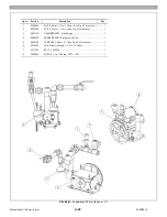
Fig. 04B - Feedwater Pump Hookup–C2
FIG. 04B -
Feedwater Pump Hookup – C2
Item
Part No.
Description
Qty.
1
UH30824
VALVE, Relief, 1/2 in., 275 psi (See Fig. 07 for details.) ............ 1
2
UH23304
VALVE, Check, 1 1/4 in. (See Fig. 06 for details.) ..................... 1
3
UH27215
CHAMBER ASSY, Intake Surge ................................................ 1
4
UH24615
SNUBBER ASSY, Discharge, 300 psi ........................................ 1
5
UH39671
PUMP ASSY, Water, C2 (See Fig. 05B for details.) ................... 1
6
0030484
VALVE, Ball, lockable, 1 1/2 in., 1000 psi ................................. 1
7
0031462
BELT, V, 3VX500 ..................................................................... 1
8
0038193
MOTOR, 3/4 hp, 1200 rpm, TEFC ............................................. 1
0041360
MOTOR, 2 hp, 1800 rpm, TEFC ................................................ 1
1
2
3
4
5
7
8
6
Summary of Contents for Steam Master CSMG-15
Page 1: ...STEAM MASTER SERIES USER MANUAL Cover CSMG 15 30 40 R027880B 20190603 ...
Page 8: ...vi The controls and features may differ depending on the unit s size and specifications ...
Page 9: ...vii The controls and features may differ depending on the unit s size and specifications ...
Page 14: ...Specifications_CSM_a fm xii 11 22 2018 This page intentionally left blank ...
Page 44: ...Sect05_CSMG_a fm 5 6 11 26 2018 Steam Master Instruction Manual NOTES ...
Page 68: ...HeatingSect_SM15_a fm A 2 04 30 2019 Fig 01A Main Heating Section SM15 ...
Page 69: ...04 30 2019 A 3 HeatingSect_SM15_a fm FIG 01A Main Heating Section SM15 ...
Page 70: ...HeatingSect_SM15_a fm A 4 04 30 2019 Fig 01B Economizer Stack Outlet Kit SM15 ...
Page 71: ...04 30 2019 A 5 HeatingSect_SM15_a fm FIG 01B Economizer Stack Outlet Kit SM15 ...
Page 72: ...HeatingSect_SM30_b fm A 6 12 05 2018 Fig 01C Main Heating Section SM30 ...
Page 73: ...12 05 2018 A 7 HeatingSect_SM30_b fm FIG 01C Main Heating Section SM30 ...
Page 74: ...HeatingSect_SM30_b fm A 8 12 05 2018 Fig 01D Economizer Coil SM30 ...
Page 75: ...12 05 2018 A 9 HeatingSect_SM30_b fm FIG 01D Economizer Coil SM30 ...
Page 76: ...HeatingSect_SM45_b fm A 10 04 30 2019 Fig 01C Main Heating Section SM40 ...
Page 77: ...04 30 2019 A 11 HeatingSect_SM45_b fm FIG 01C Main Heating Section SM40 ...
Page 78: ...HeatingSect_SM45_b fm A 12 04 30 2019 Fig 01D Economizer Coil SM40 Sht 1 of 2 ...
Page 79: ...04 30 2019 A 13 HeatingSect_SM45_b fm FIG 01D Economizer Coil SM40 ...
Page 86: ...Sep Trap PressMfld_SM153040_b fm A 20 04 30 2019 Fig 02E Pressure Indicating System ...
Page 87: ...04 30 2019 A 21 Sep Trap PressMfld_SM153040_b fm FIG 02E Pressure Indicating System ...
Page 90: ...PumpHkup C1 C2_parts_a fm A 24 03 05 2019 Fig 05A Pump Assy C1 ...
Page 91: ...03 05 2019 A 25 PumpHkup C1 C2_parts_a fm FIG 05A Pump Assy C1 ...
Page 92: ...03 05 2019 A 26 PumpHkup C1 C2_parts_a fm Fig 05B Pump Assy C2 ...
Page 93: ...PumpHkup C1 C2_parts_a fm A 27 03 05 2019 FIG 05B Pump Assy C2 ...
Page 98: ...Blank_Left fm A 32 08 16 2017 This page intentionally left blank ...
Page 106: ...R027906A 2018 10 22 ...
Page 107: ...NOTES ...
Page 108: ...Steam Generator Instruction Manual This page intentionally left blank ...
Page 109: ......


