GasBurnerSys_SM15-30-40_a.fm
A-29
04/30/2019
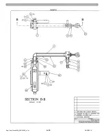
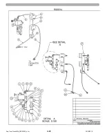
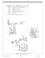
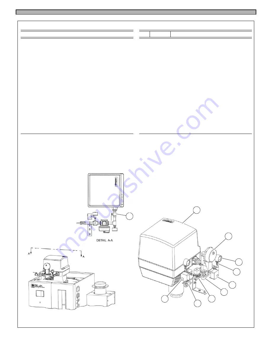
Fig. 09 - Fuel Gas System
FIG. 09
Fuel Gas System
3
6
7
5 2x
2x
9
Item
Part No.
Description
Qty.
Item
Part No.
Description
Qty.
1
0044420
BURNER, Compact, Gas, WG40N/1-A ............. 1
6
0022088
VALVE, Ball, bronze, 1/4 in. ............................2
0044627
BURNER, Compact, Gas, WG30N/1-C ............. 1
7
- - -
SWITCH, Pressure, 0.4 in. – 4.0 in. w.c., ..........1
0044628
BURNER, Compact, Gas, WG20N/1-C ............. 1
GAO-A4-4-3, Dungs 266920
2
- - -
VALVE, Ball, bronze, 3/4 in, DN20 ................... 2
8
- - -
SWITCH, Pressure, 1.0 in. – 20.0 in. w.c., .........1
PN30W-MOP5 17/80
GML-A4-4-4, Dungs 266945
- - -
VALVE, Ball, bronze, 1 in, DN25 CW510L ........ 2
- - -
SWITCH, Pressure, 12.0 in. – 60.0 in. w.c., .......1
3
- - -
ACTUATOR, Gas Valve, P.O.C., SKP25.011U1 . 1
GML-A4-4-6, Dungs 266947
(Clayton equivalent part no.: 0039296)
9
- - -
VALVE, Solenoid, 3/4 in., 120v / 60Hz, Asco, .....1
4
- - -
BODY, Gas Valve, 3/4 in., VGG10.204U ........... 1
8214G030
(Clayton equivalent part no.: 0036993)
- - -
VALVE, Solenoid, 1 in., 120v / 60 Hz, Asco, ......1
- - -
BODY, Gas Valve, 1 in., VGG10.254U .............. 1
8214G251
(Clayton equivalent part no.: 0032792)
5
- - -
GAUGE, Pressure, 2 1/2 in., in. w.c. / kPa, ....... 2
0 – 3 psi (0 – 20.5 kPa)
8
4
2
1
2
Summary of Contents for Steam Master CSMG-15
Page 1: ...STEAM MASTER SERIES USER MANUAL Cover CSMG 15 30 40 R027880B 20190603 ...
Page 8: ...vi The controls and features may differ depending on the unit s size and specifications ...
Page 9: ...vii The controls and features may differ depending on the unit s size and specifications ...
Page 14: ...Specifications_CSM_a fm xii 11 22 2018 This page intentionally left blank ...
Page 44: ...Sect05_CSMG_a fm 5 6 11 26 2018 Steam Master Instruction Manual NOTES ...
Page 68: ...HeatingSect_SM15_a fm A 2 04 30 2019 Fig 01A Main Heating Section SM15 ...
Page 69: ...04 30 2019 A 3 HeatingSect_SM15_a fm FIG 01A Main Heating Section SM15 ...
Page 70: ...HeatingSect_SM15_a fm A 4 04 30 2019 Fig 01B Economizer Stack Outlet Kit SM15 ...
Page 71: ...04 30 2019 A 5 HeatingSect_SM15_a fm FIG 01B Economizer Stack Outlet Kit SM15 ...
Page 72: ...HeatingSect_SM30_b fm A 6 12 05 2018 Fig 01C Main Heating Section SM30 ...
Page 73: ...12 05 2018 A 7 HeatingSect_SM30_b fm FIG 01C Main Heating Section SM30 ...
Page 74: ...HeatingSect_SM30_b fm A 8 12 05 2018 Fig 01D Economizer Coil SM30 ...
Page 75: ...12 05 2018 A 9 HeatingSect_SM30_b fm FIG 01D Economizer Coil SM30 ...
Page 76: ...HeatingSect_SM45_b fm A 10 04 30 2019 Fig 01C Main Heating Section SM40 ...
Page 77: ...04 30 2019 A 11 HeatingSect_SM45_b fm FIG 01C Main Heating Section SM40 ...
Page 78: ...HeatingSect_SM45_b fm A 12 04 30 2019 Fig 01D Economizer Coil SM40 Sht 1 of 2 ...
Page 79: ...04 30 2019 A 13 HeatingSect_SM45_b fm FIG 01D Economizer Coil SM40 ...
Page 86: ...Sep Trap PressMfld_SM153040_b fm A 20 04 30 2019 Fig 02E Pressure Indicating System ...
Page 87: ...04 30 2019 A 21 Sep Trap PressMfld_SM153040_b fm FIG 02E Pressure Indicating System ...
Page 90: ...PumpHkup C1 C2_parts_a fm A 24 03 05 2019 Fig 05A Pump Assy C1 ...
Page 91: ...03 05 2019 A 25 PumpHkup C1 C2_parts_a fm FIG 05A Pump Assy C1 ...
Page 92: ...03 05 2019 A 26 PumpHkup C1 C2_parts_a fm Fig 05B Pump Assy C2 ...
Page 93: ...PumpHkup C1 C2_parts_a fm A 27 03 05 2019 FIG 05B Pump Assy C2 ...
Page 98: ...Blank_Left fm A 32 08 16 2017 This page intentionally left blank ...
Page 106: ...R027906A 2018 10 22 ...
Page 107: ...NOTES ...
Page 108: ...Steam Generator Instruction Manual This page intentionally left blank ...
Page 109: ......


