Repair or Warranty Contact
Clayton Associates, Inc. • 1650 Oak Street • Lakewood, New Jersey 08701 • P.+1-732-363-2100 F.+1-732-364-6084
TV-1400
Page 12
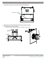
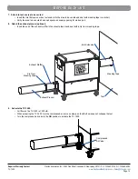
5. Attach the compressed air line.
• Verify the TV-1400 compressed air valve is in the
OFF
position.
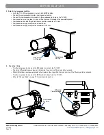
• Connect the compressed air line to a compressed air source.
• Connect the compressed air line coupler to the compressed air plug on the TV-1400.
• Compressed air must be clean, dry, and oil free to prevent blockage of the pneumatic system.
• Compressed airline and fittings must have a minimum diameter of 1/2 inch.
• Compressed air supply must provide at least 90 psi.
• Compressed air supply must provide a minimum of 50 cfm.
6. Check the Filters.
• Turn the compressed air valve to the
ON
position to activate the TV-1400.
• Check the differential pressure gauge to determine if one or more filters need to be replaced.
• If the differential pressure gauge exceeds the maximum level specified, then one or more of the filters need to be replaced.
• Turn the compressed air valve to the
OFF
position to deactivate the TV-1400.
• Refer to “Change Filters” on page 15 for complete information.
BEFORE EACH USE
TV-1400_030
Compressed
Air Coupler
Compressed
Air Plug
TV-1400_031
Compressed
Air Valve
TV-1400_032
Differential
Pressure Gauge

