Copyright © 2016 Clayton Associates, Inc. • 1650 Oak St. • Lakewood, NJ 08701
800-248-8650 • www.VacuumSanding.com
5
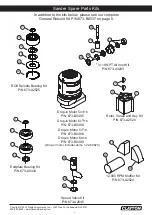
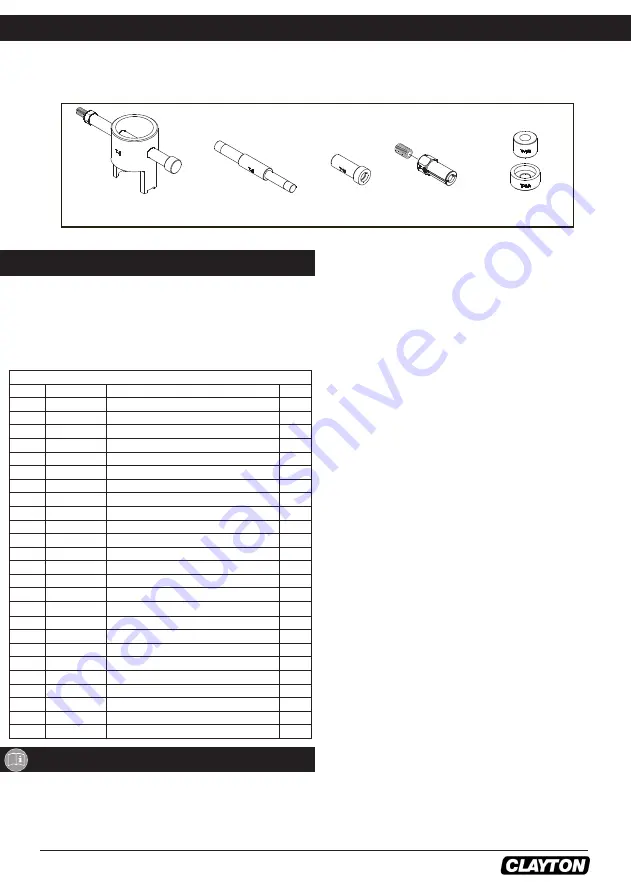
Clayton Service Tools and Accessories
When a Clayton ROS needs to be serviced, we offer a tool kit to make the disassembly/assembly fast and easy. The Service
Tools are highly recommended for use with the Overhaul Service Kit. NOTICE: To receive any expressed or implied warranty,
the tool must be repaired by an authorized Clayton Service Center. The 5 in. and 6 in. TwoHAND™ Random Orbital Sanders
Service Instructions section provided are for use after completion of the warranty period.
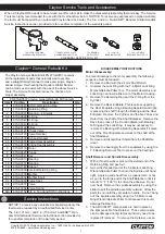
UNIVERSAL SERVICE TOOL KIT
T-6 MOTOR LOCK RING
WRENCH/SPINDLE PULLER
T-8 MOTOR FACE PLATE
BEARING REMOVAL TOOL
T-13 BEARING
PRESS TOOL
T-9 12 mm ID
BEARING PULLER
T-1 ROS SPINDLE
BEARING PRESS TOOLS
DISASSEMBLY INSTRUCTIONS
Motor Disassembly:
To prevent damage to the motor assembly the following
sequence must be followed:
1. Remove the Pad with the 24 mm Pad Wrench.
2. Unscrew the Lock Ring with the T-6 Motor Lock Ring
Wrench/Spindle Puller Tool. The motor assembly and
Lock Ring can now be lifted out of the Motor Housing.
3. Remove the Retaining Ring and the O-Ring from the
Cylinder.
4. Remove the Rear Endplate. This requires supporting
the Rear Endplate using a Bearing Separator and light
-
ly pressing the shaft through the Bearing and the Rear
Endplate. Remove the Cylinder and the five Vanes and
Rotor from the shaft of the Shaft Balancer. Remove the
Keys then press off the Front Endplate (with Bearing),
O-Ring and the Lock Ring. It may be necessary to
remove the Bearing with a Bearing Separator if it came
out of the Front Endplate and stuck to the shaft of the
Shaft Balancer.
5. Remove and discard Dust Shield from the Shaft Bal
-
ancer.
6. Remove the bearing(s) from the endplates by using the
T-8 Bearing Removal Tool to press out the bearings.
Shaft Balancer and Spindle Disassembly:
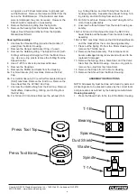
1. With a thin screwdriver pick out the slotted end of the
Retaining Ring and peel out.
2. Screw the threaded end of the T-6 Motor Lock Ring
Wrench/Spindle Puller Tool into the Spindle until hand
tight. Apply a gentle heat from a propane torch or hot
air gun to the large end of the Shaft Balancer until it is
about 212° F (100° C) to soften the adhesive. Do not
over heat. Remove the spindle assembly by using the
slider to pull the spindle assembly outward. Allow the
parts to cool until they are safe to handle. Do not “bang
out” the spindle assembly using the T-6 Motor Lock
Ring Wrench/Spindle Puller Tool because this could
damage the Bearing.
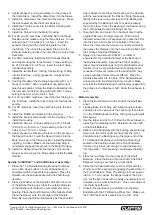
3. The AirSHIELD™ components are held in place by
the light press fit of the Retainer. These components
can be damaged during removal and may need to be
replaced if removed. To remove the Retainer, use an
NOTICE: To receive any expressed or implied warranty, the
tool must be repaired by an authorized Service Center.
The 5 in (127 mm.) and 6 in. (150 mm) TwoHAND™ Ran
-
dom Orbital Sander Service Instructions section provided is
for use after completion of the warranty period.
Service Instructions
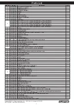
PN 673-B0537 Clayton General Rebuild Kit Contents
Item
Part No.
Description
Qty.
1
673-A0040 External Retaining Ring
1
17
673-A0090
Retaining Ring
1
2
673-A0021 Bearing – 2 Shields
1
59
673-A0628
O-Ring
1
5
673-A0042
O-Ring
1
54
673-A0043
O-Ring
1
14
673-A0122
Filter
1
15
673-A0121 Check Valve
1
16
673-A0120 Valve Retainer
1
41
673-A0500 Exhaust Gasket
1
35
673-A0655 Valve Stem Assembly
1
40
673-A0730 Airline Seal Assembly
1
6
673-B0118
Rotor
1
7
673-A0445 Vanes
5
8
673-A0041
Key
2
10
673-A0019
Bearing
1
18
673-A0751
Bearing
1
19
673-A1767
Spacer
1
56
673-A0039
Internal Retaining Ring
1
60
673-A0776 Muffler
2
27
673-A0032 Muffler Insert
1
37
673-A0009 Valve Seat
1
38
673-A0007 Valve
1
39
673-F0094 Valve Spring
1
N/A 673-A2152 5/6 in. TwoHand ROS Instructions
1
Clayton
™
General Rebuild Kit
The Clayton General Rebuild Kit PN 673-B0537 contains
all the replacement parts that naturally wear over time
and a straightforward manual to make servicing a Clayton
sander simple. Overhauling the Random Orbital Sander
can be made even easier with the use of the above Service
Tools. The Service Tools also reduce the chance of im
-
proper assembly.


