10
FURNACE ASSEMBLY
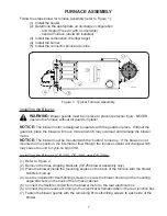
Air Discharge Configurations:
Your Clean Energy Heating System may be installed in one of two ways:
1.
Unit Heater
- Louvers are installed over the air outlet opening(s) to direct the hot air
flow in the desired direction.
2. Central
Furnace
(Static
Pressure)
- Duct work applications with less than 0.30”
W.C.
(inches of water column).
Louvers are NOT installed. Ductwork is installed over the side
air outlet opening(s) to direct the hot air flow.
NOTICE:
A qualified electrician should check the amp draw of the blower motor. Do not
operate the blower motor over 85% of the amp rating on the motor nameplate.
1.
Unit Heater Configuration
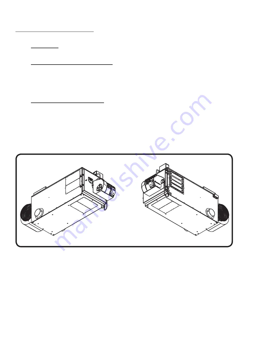
There are several options for mounting the louvers on a unit heater for free air applications.
Refer to Figures 3, 4, and 5. Cover the unused air outlet openings with the blank covers
provided (one is painted and one is galvanized). The blank covers can be split in two.
NOTICE:
When splitting a side opening horizontally, the louvers should be positioned in the
top half of the air outlet opening. When splitting a side opening vertically, the louvers should
be positioned in the front (closest to the burner) half of the air outlet opening.
Figure 3: Installing the Louvers
One Side Air Outlet Fully Open
CE70159
Summary of Contents for CE-140
Page 50: ...50 NOZZLE ADAPTER HEATER BLOCK ASSEMBLY 2 3 19 5 7 8 15 9 17 14 18 16 13 1 4 6 10 11 12 ...
Page 52: ...52 MANIFOLD BLOCK ASSEMBLY 8 6 2 1 4 17 3 9 5 7 12 13 14 15 16 18 19 11 10 ...
Page 58: ...58 3 4 6 1 2 5 CE 140 180 BLOWER ...
Page 62: ...62 2 3 4 5 6 1 CE 250 BLOWER ...
Page 66: ...66 CE 330 BLOWER 12 8 7 4 13 1 2 3 5 6 9 10 11 ...
Page 70: ...70 CE 440 BLOWER 12 8 7 4 13 1 2 3 5 6 9 10 11 ...


