Installing the Combustion Chamber Target:
NOTICE:
Damage to the combustion chamber may occur if the furnace is used with a
damaged or missing target. Inspect the target regularly for proper positioning and wear.
(1) Refer to Figure 6 to view the proper position of the combustion chamber target.
(2) Open the front door of the furnace by loosening the two over-center latches and swinging
the door open.
(3) Guide the target toward the back of the combustion chamber. Hang the loop on the back
of the target on the hook welded to the back of the combustion chamber.
(4) Close the front door and secure the two over center-latches.
13
Installing the Burner:
Figure 6: Proper Position of the Combustion Chamber Target
NOTICE:
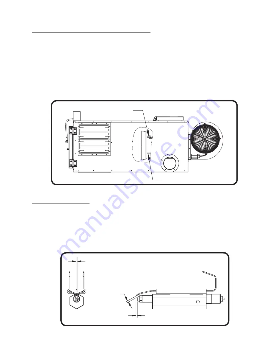
The nozzle, electrode, and retention head may need adjustment after shipping and
installation. The nozzle should remain centered in the retention head. Refer to Figure 7 for
proper dimensions.
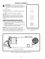
(1) Remove the two serrated flange nuts from the front door.
(2) Slide the blast tube of the burner through the throat of the front door.
(3) Fasten the burner to the front door by tightening the two serrated flange nuts.
Figure 7: Nozzle and Electrode Settings
FURNACE ASSEMBLY
3/16" GAP
BETWEEN
ELECTRODES
AND NOZZLE
CE70018
1/8" GAP BETWEEN
ELECTRODES
ELECTRODE 1/8"
PAST NOZZLE
CE70020
Target hanging on back of
combustion chamber hook and
resting against stabilizer
Target Stabilizer
Summary of Contents for CE-140
Page 50: ...50 NOZZLE ADAPTER HEATER BLOCK ASSEMBLY 2 3 19 5 7 8 15 9 17 14 18 16 13 1 4 6 10 11 12 ...
Page 52: ...52 MANIFOLD BLOCK ASSEMBLY 8 6 2 1 4 17 3 9 5 7 12 13 14 15 16 18 19 11 10 ...
Page 58: ...58 3 4 6 1 2 5 CE 140 180 BLOWER ...
Page 62: ...62 2 3 4 5 6 1 CE 250 BLOWER ...
Page 66: ...66 CE 330 BLOWER 12 8 7 4 13 1 2 3 5 6 9 10 11 ...
Page 70: ...70 CE 440 BLOWER 12 8 7 4 13 1 2 3 5 6 9 10 11 ...


