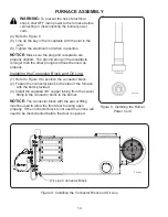
(1) Install a dedicated electrical circuit to the junction box indicated below.
FRONT ELECTRICAL BOX
by the burner on the
CE-140, CE-180, and CE-250
BACK ELECTRICAL BOX
by the blower on the
CE-330 and CE-440
(2) Connect the wires according to the label found on the inside of the junction box cover or in
the
wire diagrams section
of this manual. Use stranded copper wire to ensure a secure
connection.
19
Installing the chimney components:
WARNING:
Double wall “Class A” insulated stack must be used through any building
penetration and for any exterior stack. Unapproved stack material and/or installation
can create a fire hazard. Contact Clean Energy Heating Systems, LLC to purchase
approved stack material for your installation.
CAUTION:
Using single wall stack on the exterior of your building will cause the stack
gases to cool rapidly and adversely affect the natural draft of the furnace. This will
create a back draft and may damage critical burner components.
(1) Refer to Figure 14 for a typical through-the-roof chimney illustration and Figure 15 for a
typical through-the-wall chimney illustration.
(2) Observe the following requirements when installing the chimney:
• The CE-140, CE-180 and CE-250 furnace models require 6” I.D. stack components.
• The CE-330 and CE-440 furnace models require 8” I.D. stack components.
• Have a minimum of 10 feet vertical chimney to ensure -.02” w.c. draft over fire.
• Keep horizontal runs short. Slope any horizontal sections at least 1/4” per foot.
• Keep the stack installation simple. Multiple turns and horizontal runs will reduce the
natural draft of the furnace which may damage critical burner components.
(3) Single wall stack may be used inside the building. Observe proper clearances from
combustibles. Do not put single wall stack in areas that may create a burn hazard to
personnel.
(4) Install a barometric damper, as shown in Figures 15 and 16, so that proper draft can be
maintained. Follow the instructions provided with the damper for proper installation.
(5) Use double wall “Class A” insulated stack material when making a penetration through the
ceiling, roof or side wall of your buiding. Install proper flashing around the exterior
penetration of the stack to make a water tight seal.
(6) Install a “Class A” non-restrictive stack cap only.
CAUTION:
If your building utilizes an exhaust fan, ensure that there is adequate
make-up air available. Lack of make-up air will create a vacuum in your building
which will result in a back draft at the furnace. A back draft will damage critical burner
components.
FURNACE INSTALLATION
DANGER:
Follow manufacturers instructions and requirements for clearances (air
spaces) to combustible material for the Double Wall “Class A” Insulated chimney
material.
Summary of Contents for CE-140
Page 50: ...50 NOZZLE ADAPTER HEATER BLOCK ASSEMBLY 2 3 19 5 7 8 15 9 17 14 18 16 13 1 4 6 10 11 12 ...
Page 52: ...52 MANIFOLD BLOCK ASSEMBLY 8 6 2 1 4 17 3 9 5 7 12 13 14 15 16 18 19 11 10 ...
Page 58: ...58 3 4 6 1 2 5 CE 140 180 BLOWER ...
Page 62: ...62 2 3 4 5 6 1 CE 250 BLOWER ...
Page 66: ...66 CE 330 BLOWER 12 8 7 4 13 1 2 3 5 6 9 10 11 ...
Page 70: ...70 CE 440 BLOWER 12 8 7 4 13 1 2 3 5 6 9 10 11 ...


