background image

- 10 -

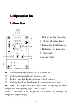
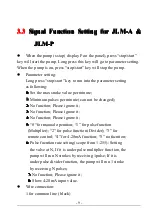
2 for 4-20mA signal input(white)

3 for pulse signal input( green)

4 for remote control (red)

4

4

4

4 Maintenance

Maintenance

Maintenance

Maintenance and

and

and

and Repair

Repair

Repair

Repair

Warning

Warning

Warning

Warning

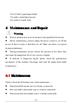
Electric maintenance must be carried out by qualified electrician.

Before maintenance, please unplug the power socket or cut off the

power. If there is relay, it should be cut off. Make sure there is no power

during maintenance.

During maintenance, please release the pressure in the tubes first,

and clean the pump head. Don’t use corrosive liquids.

If medium is dangerous liquid, please check the performance

parameters of the medium. Discharge and wash the pump head before

maintenance.

4.1

4.1

4.1

4.1

Maintenance

Maintenance

Maintenance

Maintenance

Strictly check the following items when maintenance.

Pump head bolts (make sure it is firmly connected)

Inlet and outlet tubes(make sure it is firmly connected)

Pump head and valves(make sure it is firmly connected)

Summary of Contents for Precision-24

Page 1: ...Precision 24 Manual Specification ...

Page 2: ......

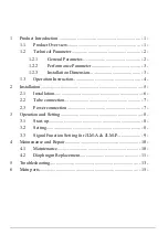
Page 3: ...llation Dimension 3 1 3 Operation Instruction 4 2 Installation 5 2 1 Installation 6 2 2 Tube connection 7 2 3 Power connection 7 3 Operation and Setting 8 3 1 Start up 8 3 2 Setting 8 3 3 Signal Function Setting for JLM A JLM P 9 4 Maintenance and Repair 10 4 1 Maintenance 10 4 2 Diaphragm Replacement 11 5 Troubleshooting 13 6 Main parts 15 ...

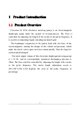
Page 4: ...e pulse frequency It is used for transmitting liquid including mordant liquid The diaphragm reciprocates in the pump head with the force of the electromagnetic causing the change of the volume and pressure which make the check valves open and close automatically Thus the liquid is sucked and discharged The rated output volume of this electronic diaphragm metering pump is 1 15 l h and its correspon...

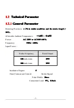
Page 5: ...stroke stroke stroke stroke length length length length 30 30 30 30 Allowable Ambient Temperature 10 10 10 10 45 45 45 45 Power AC AC AC AC 220V 220V 220V 220V or or or orAC110V AC110V AC110V AC110V 10 10 10 10 Frequency 50Hz 50Hz 50Hz 50Hz 60Hz 60Hz 60Hz 60Hz Input Power Insulation Degree F F F F Outer Connection Control Stroke Signal Pulse Width 20ms 20ms 20ms 20ms Connection Load 5V 5V 5V 5V 0 ...

Page 6: ... re re re re Bar Bar Bar Bar Stroke Stroke Stroke Stroke Control Control Control Control Pulse Pulse Pulse Pulse frequency frequency frequency frequency Stroke min Stroke min Stroke min Stroke min Calib Calib Calib Calib er er er er mm mm mm mm 3 8 7 6 20 100 0 180 5 1 2 3 1 2 3 1 2 3 1 2 3 Installation Installation Installation Installation Dimension Dimension Dimension Dimension ...

Page 7: ...hree digitals show the state of the frequency While the last three digitals are off the pump stops working Mark 2 on the picture is the stroke knob for adjusting the stroke length The best adjusting range is 30 100 Mark 3 and mark 4 on the picture are buttons for adjusting the frequency in percentage 1 Displaying the frequency 2 Stroke adjusting knob 3 Increasing the frequency 4 Reducing the frequ...

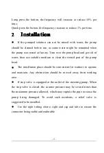
Page 8: ...ter then use suitable medium to clean the wetted part of the pump head The installation place should be convenient for workers to operate and maintain Any obstruction should be moved away from working area If stop valve is equipped at the outlet of the metering pump When the stop valve is closed the counter pressure may be several times than the maximum pressure allowed which may rupture the pipe ...

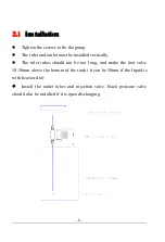
Page 9: ...inlet and outlet must be installed vertically The inlet tubes should not be too long and make the foot valve 10 30mm above the bottom of the tank it can be 50mm if the liquid is with heavier dirt Install the outlet tubes and injection valve Back pressure valve should also be installed if it is open discharging ...

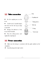
Page 10: ...onnection connection Make sure the voltage is consistent with the grade marked on the nameplate Insert the plug to the right socket Put the coupling nut on the hose Cut the hose at suitable length and insert on the end cap as deep as possible Enlarge the diameter of the hose a little if needed Press the tubing sleeve and tighten the coupling nut ...

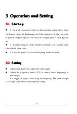
Page 11: ...ressure regulating valve Or loose the coupling nut to discharge the air l Start the pump to check whether the liquid is out from the outlet tube or the bypass valve l Close the bypass valve when the pump works normally 3 2 3 2 3 2 3 2 Setting Setting Setting Setting Adjust strok knob to adjust the stoke length Adjust the frequency button to control stoke frequency in percentage It is suggested adj...

Page 12: ...e value per minute 1 1 1 1 Minimum pulses per minute can not be changed 2 2 2 2 No function Please ignore it 3 3 3 3 No function Please ignore it 4 4 4 4 No function Please ignore it 5 5 5 5 0 for manual operation 1 for pulse function Multiplier 2 for pulse function Divider 3 for remote control 4 for 4 20mA function 5 no fucntion 6 6 6 6 Pulse fucntion rate setting scope from 1 255 Setting the val...

Page 13: ...d be cut off Make sure there is no power during maintenance During maintenance please release the pressure in the tubes first and clean the pump head Don t use corrosive liquids If medium is dangerous liquid please check the performance parameters of the medium Discharge and wash the pump head before maintenance 4 1 4 1 4 1 4 1 Maintenance Maintenance Maintenance Maintenance Strictly check the fol...

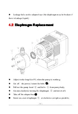
Page 14: ...agm Diaphragm Replacement Replacement Replacement Replacement Adjust stroke length to 0 when the pump is working Cut off the power loosen the bolts Pull out the pump head and bolts from pump body Counter clockwise turning the diaphragm and turn it off Take off the adapter base Screw on a new diaphragm at clockwise as tight as possible ...

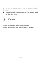
Page 15: ...he drain hole oriented downward Remount the pump head back Take care of the direction of inlet and outlet check valves Warnings Leakage hole on the adapter base must be downward Recheck the screws on th pump head tighten them if necessary ...

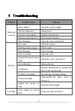
Page 16: ... it No Flow Not work Check the power Offering tank is empty Fill the tank Pipe blockage Clean the pipe Valve is closed Open the valve Granule block off check valve Check the valve and clean it Air in the pipe Release the air Cavitations Increase the pressure of suction and shorten the suction pipe Problem of priming Re priming checking leakage Filter is blocked Disassemble the filter clean or chan...

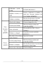
Page 17: ...lve leakage Clean or change the valve Suction pipe leakage Find the leakage position and solute the problem Filter is blocked Disassemble the filter clean or change it Medium is changed Check the viscosity and other parameters Blowhole of the offering tank is blocked Open the blowhole Flow is unstable Suction piping leakage Find the leakage position and solute the problem Medium cavitations Increa...

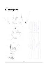
Page 18: ... 15 6 6 6 6 Main Main Main Main parts parts parts parts ...

Reviews: