background image

26

OPERATIONS MANUAL

27

RHINO-MAT

Maintenance

DISCONNECT FROM POWER SOURCES BEFORE PERFORMING 

MAINTENANCE PROCEDURES.

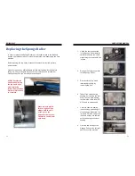
Brush Roller Maintenance

Period Between Maintenance: Every 2 weeks or as needed

Date of last maintenance: ___________

Maintenance consists of removing tangled hair, threads and other foreign 
objects from brush roller using pliers or fingers.

Access Point:

 Top Hood; always utilize the included hood stands any time 

you are doing maintenance on interior components.

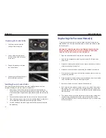
Extraction Drum Maintenance

Period Between Maintenance: Every month or as needed

Date of last maintenance: ___________

Maintenance consists of opening the hatch and cleaning the extraction drum 
of any built up debris and particulates over a period of time.   


Access Point:

 Bottom front panel; turn both keys simultaneously and the 

panel aside during maintenance.

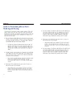
Drainage Hose System Maintenance

Period Between Maintenance: Every month or as needed

Date of last maintenance: ___________

Maintenance consists of disconnecting drainage hoses and clearing them of 
any debris and particulates that maycomponents. Build up over a period of 
time. A clogged drainage hose may lead to damage to interior.

Access Point:

 Front access panels; turn both keys simultaneously to open 

bottom panel. Utilize a Philips head screwdriver to remove two screws and 
open the upper front panel. 

Water Drainage Tray Maintenance

Period Between Maintenance: Every month or as needed

Date of last maintenance: ___________

Maintenance consists of cleaning out the water drainage tray of any dirt and 
debris left behind from the washing process which can eventually lead to a 
clog in the interior drainage hose.

Access Point:

 Remove the bottom front access panel first using the two 

keys provided and the remove the top front access panel using a Philips 
head screwdriver.

Extraction Tray Slit Maintenance

Period Between Maintenance: Every 12 to 18 months after purchase, or 

with replacement of Sponge Roller

Date of last maintenance: ___________

Maintenance consists of clearing any clogged slits on the extraction tray. 
Manufacturer highly recommends this maintenance to be performed with the 
replacement of the Sponge Roller. 

Access Point:

 Top Hood; always utilize the included hood stands any time 

you are doing maintenance on interior components. Removal of Sponge 
Roller may be required in order to access the full Extraction Tray. 

Gear and Chain Maintenance

Period Between Maintenance: Every 12 to 18 months after purchase.

Date of last maintenance: ___________

Maintenance consists of wiping away old lubricant and applying new 
lubricant to all gears and chains.

Access Point:

 Left and Right Side Access Doors; turn both keys at the 

same time when opening each door.

FLIP CIRCUIT BREAKER SWITCH TO OFF AND DISCONNECT 

FROM POWER SOURCES BEFORE REPLACING ANY ELECTRICAL 

COMPONENTS. 

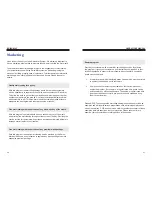
Vacuum Motor(s)

Effective life expectancy: 1 to 2 years depending on usage

Date of last replacement: ___________

Maintenance consists of an inspection to ensure the vacuum motors are still 
in working condition after long periods of use. Users should not continue to 
use the machine upon discovery of any damages until replacement motors 
are installed.

Access Point:

 Back access panels; turn both keys simultaneously to open 

bottom 

panel. 


Warning: DO NOT insert fingers into any part of the vacuum motor 

where moving parts are exposed!

Summary of Contents for Rhino-Mat RHM-CS

Page 1: ......

Page 2: ...able and Portable Heavy duty construction Carbon Steel and Stainless Steel models are available for both indoor and outdoor use Integrated auto heating system designed for use year round Large Roller wheels are included for easy movement and storage Adjustable steel mounts are available for stationary application Versatile Full Serve and Self Serve models to adjust to the needs of your business Fu...

Page 3: ...iries to qualified service personnel Servicing is required when the machine has suffered severe damage which includes but is not limited to damage to the power cord or plug or when the machine does not operate or function normally IMPORTANT TO ENSURE THE SAFE AND EFFECTIVE USE OF THIS EQUIPMENT PLEASE READ THE SAFETY AND OPERATIONAL INSTRUCTIONS THOROUGHLY SAVE ALL DOCUMENTATION FOR FUTURE REFEREN...

Page 4: ... Valve 6 Chemical Container Left Side Panel Part Identification Included Stand Alone Parts BEFORE OPERATING THE MACHINE ALL END USERS SHOULD KNOW HOW TO USE THE MACHINE AND ITS COMPONENTS PROPERLY MISHANDELING AND NEGLECT CAN LEAD TO IRREVERSABLE DAMAGES TO THE MACHINE NOT COVERED UNDER MANUFACTURER S WARRANTY Getting Started Opening Top Hood Open the top hood by sliding fingers into the mat feedi...

Page 5: ...h on both arms 4 Clamp and position exterior drainage hose pointing down at drain or connect extended drainage line as needed at your location 5 Connect line from water source to the water valve inside of the Left Side Panel REMEMBER to apply hose clamp tightly A loose hose clamp will result in leakage 6 Pull power cord through the cut out hole and connect the End Plug not included 7 Plug in to a ...

Page 6: ...r first then the plastic tightner as shown Apply the power connection circuit you should hear a click sound Check to make sure the connection is properly attached Insert a 5 8 inch standard hose for your water connection Secure tightly with the fastener provided with the unit Fill up the chemical soultion in porvided 1 gallon jug Secure the heat tape to the water connection Pull the electrical con...

Page 7: ...the machine has been setup and placed in its final operating location configuration consists of two final steps Run Time MM SS SW 1 SW 2 SW 3 SW 4 SW 5 SW 6 01 00 OFF OFF OFF OFF OFF OFF 01 30 OFF OFF OFF OFF OFF 02 00 OFF OFF OFF OFF OFF 02 30 OFF OFF OFF OFF 03 00 OFF OFF OFF OFF OFF 03 30 OFF OFF OFF OFF 04 00 OFF OFF OFF OFF 04 30 OFF OFF OFF 05 00 OFF OFF OFF OFF OFF 05 30 OFF OFF OFF OFF 06 ...

Page 8: ... you have these two numbers plug them into the following equation _______________ ______________ _______________ 3 Finally once you have the DIP Switch Settings for Time find the number under the Seconds column on the Control Box DIP SW Chart for Setting Time Located on Page 15 These are the settings that DIP switches 1 5 should be set to NOTE You will need to round the number up or down if you en...

Page 9: ...r amount to be charged per cycle is 2 00 which equals 8 quarters or 8 pulses Now the equation 180 seconds 8 quarters 22 5 23 The Configuration settings for length of time per cycle Seconds DIP SW 1 DIP SW 2 DIP SW 3 DIP SW 4 DIP SW 5 23 OFF OFF DIP SW Chart for Setting Time The Configuration settings for dollar amount to be charged per cycle Coin DIP SW 6 DIP SW 7 DIP SW 8 23 OFF DIP SW Chart for ...

Page 10: ...ceptor as usual It is best to use 6 different coins since there are typically slight variations from coin to coin 6 After the 6th sample coin is deposited the LED will flash red green a few times to indicate the LEARN procedure is complete and the coin parameters are stored in memory CONFIGURING THE HAWK XEPTOR COIN ACCEPTOR COIN UN LEARN PROCEDURE 1 Slide the front cover up and turn the rotary sw...

Page 11: ...on holds no responsibility for claims made by MEI Group AE2400 Bill Validator is supported directly by MEI Group Clean World Distribution Inc can only provide basic support or replacement of the component in the event of a catastrophic failure For all other support please contact MEI Technical directly via their toll free number 800 345 8172 or on the web at www meitechnical com ...

Page 12: ...down Press the green Start Button to begin the cycle Collect the finished mat from the catch rack to the rear of the machine Easy Operation Guide Self Serve Select water switch to On or Off position Insert first mat face down Insert payment to begin the cycle Collect the finished mat from the catch rack to the rear of the machine ...

Page 13: ...erly Frequently Asked Questions Q Why is water not flowing properly from the drain hose A The drain hose may be clogged due to an excess of waste Make sure the drain hose clamp is tightly secured Be sure drain hose is pointing in a downward position Drain hose must not be bent or in an upright position WARNING In select models the Drain Hose must be completely pulled out from inside machine to all...

Page 14: ...hing process which can eventually lead to a clog in the interior drainage hose Access Point Remove the bottom front access panel first using the two keys provided and the remove the top front access panel using a Philips head screwdriver Extraction Tray Slit Maintenance Period Between Maintenance Every 12 to 18 months after purchase or with replacement of Sponge Roller Date of last maintenance ___...

Page 15: ...nt Sponge Roller Effective life expectancy 1 to 2 years depending on usage Date of last replacement ___________ Maintenance consists of an inspection to ensure the surface of the Sponge Roller is intact A worn out Sponge Roller will result in mats not being pressed down tightly enough against the extraction tray to ensure proper drying of mats It is highly recommended that the Sponge Roller be rep...

Page 16: ...in reverse order 1 Insert the new Brush Roller by sliding the shorter side less rod is exposed into the right side hole Push as far as needed to get the left side into its respective hole 2 Reattach and lock the bearing assembly and lock ring into place in the Right Side Door panel 3 Move over to the Left Side Door Panel reattach the bearing assembly and lock ring into place 4 Next slide the small...

Page 17: ...e is complete When removing bolts for bearing housings always hold the bolt or the nut on the opposite side in place Otherwise the bolt will spin freely 1 Unlink the chain connected to the Sponge Roller gear by carefully removing the chain clip holding the removable link in place 2 Remove the Gear connected to the Sponge Roller 3 Disconnect the Top Hood retaining bar spring by removing the bolt 4 ...

Page 18: ...ecessary to file down any bumps or scars on the Sponge Roller rod in order for the gear to slide on smoothly Any resistance felt may indicate a spot that needs to be filed down 6 Once the Sponge Roller gear is aligned and in place lock it down using an Allen wrench 7 When re connecting the chain be sure to run the chain UNDER the swinging arm gear not over it before reattaching the locking links I...

Page 19: ... a Philips head screwdriver to remove two screws to open the top front panel DISCONNECT THE MACHINE FROM THE PRIMARY POWER SOURCE PRIOR TO COMPLETING ANY OF THE FOLLOWING PROCEDURES FAILURE TO DO SO WILL LEAD TO SEVERE INJURY 1 Open the bottom front panel using the two keys provided 2 Open the top front panel by removing two screws with a Philips head screw driver 3 Disconnect the two power cables...

Page 20: ...ains Please note it is highly recommended that a low foam or a non foaming upholstery cleaner be used Depending on the materials that some mats consist of they may not always come out as dry as is possible All Rhino Mat systems come equipped with Water On Off toggle switches In the event that mats come out feeling moist or wet to the touch switch the water off and run the mat through again to dry ...

Page 21: ...the service for free for customers who purchase any wash periodically will help to increase over all traffic to your location Free mat cleaning with the purchase of any premium wash package With this program the quality mat cleaning service provided by the Rhino Mat would be used as an incentive to upgrade any wash package to a more expensive premium package Reward program Provide your customers w...

Page 22: ...y will stop as the system builds up to full pressure To actuate injector turn the bypass screw clockwise until product begins to be drawn from the container After the fluid reaches the injector the feed rate may be adjusted to the desired rate by turning the bypass screw The maximum injection rates are shown in Table 2 For low injection rates it is advisable to set the bypass screw for more inject...

Page 23: ...ion is removed CAUTION When servicing make sure that replacement parts have been installed according to drawing Be certain to check valve parts are in place RETURNS NO MERCHANDISE MAY BE RETURNED FOR CREDIT WITHOUT DEMA S WRITTEN PERMISSION RETURN MERCHANDISE AUTHORIZATION NUMBER REQUIRED IN ADVANCE OF RETURN WARRANTY DEMA products are warranted against defective material and workmanship under nor...

Page 24: ... TO BE VALID THE WARRANTY IS VOID IF THE DEFECT IS DUE TO NORMAL WEAR AND TEAR IS NOT COVERED BY THIS WARRANTY UPON NOTIFICATION OF A DEFECT A TECHNICIAN WILL BE OUT TO DIAGNOSE THE PROBLEM IN THE EVENT THAT A PROBLEM IS CAUSED BY ACCIDENTAL DAMAGE MISUSE ABUSE NEGLECT IMPROPER REPAIR REPLACEMENT OR ALTERATION BY UNAUTHORIZEDPERSONSORFAILURETOFOLLOWOPERATIONAL INSTRUCTIONS PROVIDED WITH THE EQUIPM...

Page 25: ......

Reviews: