42
OPERATIONS MANUAL
43
RHINO-MAT
Water Pressure
(psi)
Operating Range -
Gallons Per Minute
10
2.00 - 6.40
20
2.30 - 7.50
40
2.90 - 9.50
60
3.40 - 11.00
100
4.20 - 14.00
200
5.70 - 19.00
400
7.90 - 26.00
500
8.90 - 29.00
* 700
11.00 - 35.00
* 1000
13.00 - 41.00
* 1500
16.00 - 50.00
* 2000
18.00 - 58.00
* 3000
20.00 - 70.00
* SPECIFY – S Stainless Steel Knob – Part No.
24-32S or Part No. 24-32ST (for tips) for pressure
exceeding 700 PSI.
TABLE 1
Fluid Viscosity
(cps)
Maximum Injection
(Oz/Min)
1
40
75
8
200
4
TABLE 2
Model
Pipe Size
204 B
1/2 NPT
TABLE 4
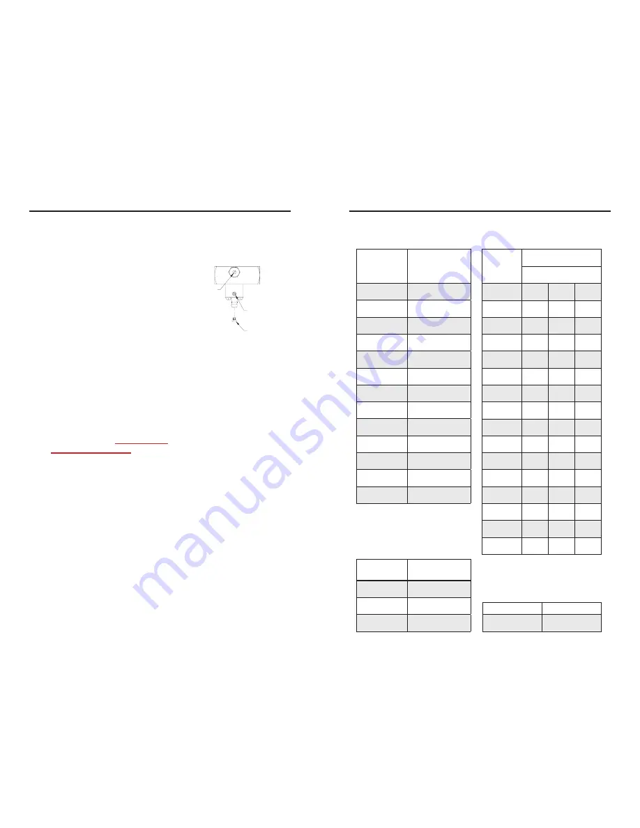
WATER BY-PASS SCREW
FIGURE 1
FINE METERING
(AS REQD.)
ADJUSTMENT
SCREW
METERING TIP
1. PARTS
A. Injector
B. Ceramic Weight.
C. Plastic tubing 8’ long with foot strainer.
2. INSTALLATION
The injector may be installed in any position in the water line with the
arrow in the direction of flow. Drop end of plastic tubing with strainer into
fluid product container. Cut tubing to convenient length, and slip open end
over injector fitting.
3. OPERATION
Warning: Use care when handling hazardous chemicals.
Note: The injector will not operate if the input water temperature
exceeds 160 degrees F.
See Fig. 1 for location of water bypass screw and fine metering
adjustment screw. Turn on water supply valve. The injector may draw
momentarily as the system is filling but normally will stop as the system
builds up to full pressure. To actuate injector, turn the bypass screw
clockwise until product begins to be drawn from the container. After the
fluid reaches the injector, the feed rate may be adjusted to the desired rate
by turning the bypass screw. The maximum injection rates are shown in
Table 2. For low injection rates, it is advisable to set the bypass screw for
more injection than required; then turn the fine metering screw clockwise
to reduce injection to the desired rate. Table 1 shows the operation range
of the injector. If the injector will not draw with the bypass screw full in,
then the water flow is below the range of the injector. If the injector draws
with the screw full out but pressure loss is excessive, then flow is above
the range of the injector. Table 3 shows the injection rates for model
204 BT using metering tips at various viscosities. Table 4 shows the
appropriate pipe size used for each injector.
DEMA ADJUSTABLE SINGLE
STAGE INJECTOR
INSTALLATION INSTRUCTIONS
Metering
Tip Color
Injection Rates (Oz/Min)
Viscosity (cps)
1
75
200
Tan
1.1
0.8
0.5
Orange
1.4
0.9
0.6
Turquoise
1.9
1.2
0.9
Pink
2.6
1.7
1.3
Clear
3.4
2.4
1.6
Brown
4.0
2.4
1.9
Red
4.9
2.9
2.2
White
6.0
3.4
2.4
Green
6.8
3.8
2.5
Blue
8.4
4.3
3.1
Yellow
13.1
5.2
3.4
Black
18.2
6.1
3.5
Purple
27.5
6.8
3.5
Gray
32.9
7.0
3.5
No Tip
39.8
7.9
3.7
All induction rates are based on a water inlet
pressure of 40 psi and operating at a full vacuum.
TABLE 3


