Principles of Operation
Heated Sample Line
6
2.3 System Operation
See below for pictures.
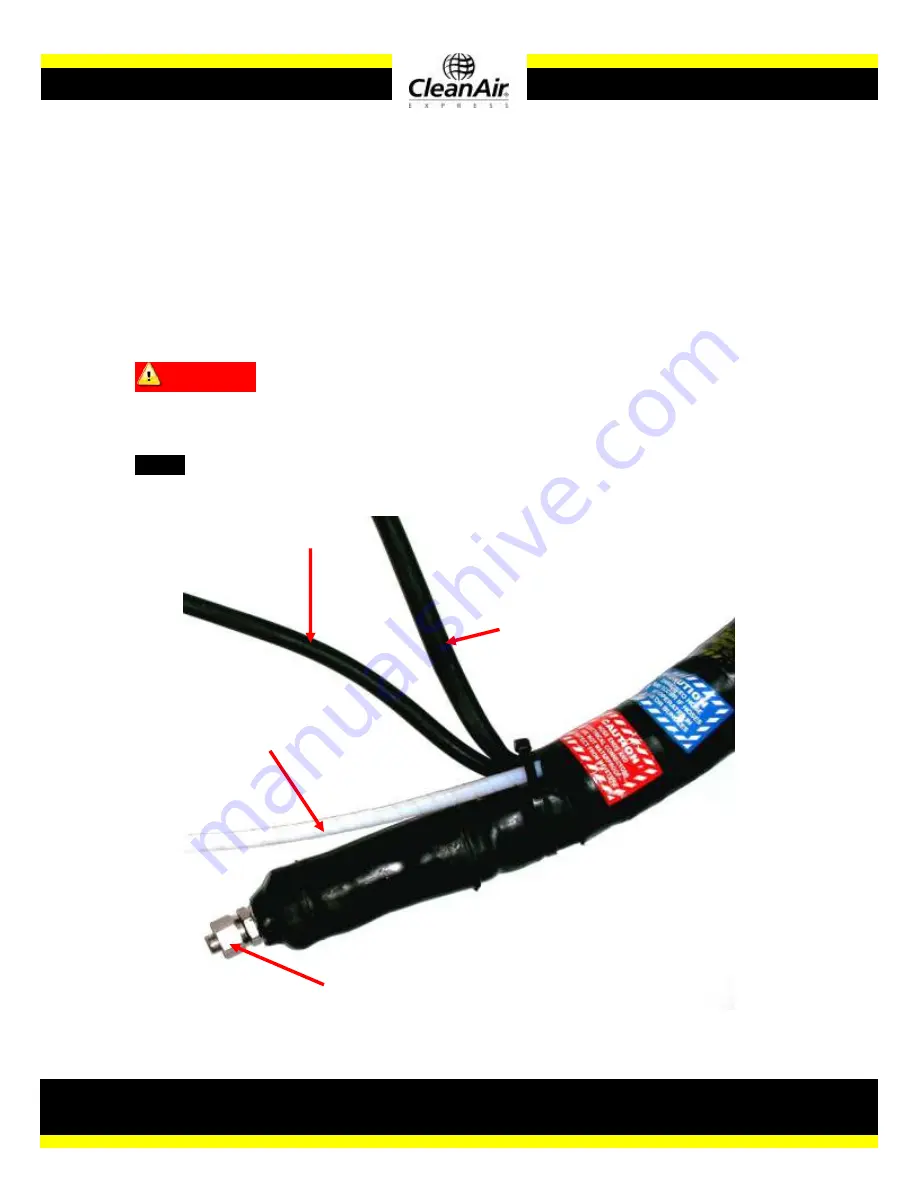
Insert one of the thermocouples
(3
,
Figure 1
)
into the corresponding input on the
temperature controller; the second is simply a spare. It is unnecessary to plug
the second thermocouple into anything. Connect the calibration gas line
(2)
and
the sample line
(1)
. Plug in the temperature controller and the heated sample
line
(4)
, as well as any other equipment (120V). Select the desired temperature.
Allow 10-15 minutes for the system to warm up then begin sampling.
CAUTION!!
–
If the light on the temperature controller does not blink when it
gets near the target temperature, overheating is very likely! The most likely
cause is a bad relay in the temperature controller.
NOTE
–
In the event of an overload, the circuit breaker on the temperature
controlling device will pop out. Simply push it in to reset.
(4)
Power
Cord
(3)
Thermocouple
Wire
(2)
Calibration
Gas Line
(1)
Sample
Line
Connection
Figure 3


