


4
5
The complete system including accessories contains
the following components:
• Powered respiratory unit -1 pc
• Battery
• Belt
• Air supply hose
• Flow indicator
• Battery charger
• Manual for use
3.2. Assemblage
1. Connect the air supply hose to the powered respi-
ratory unit making sure the screw is tight enough so
the joint is leakproof.
2.
Attach the filters to the unit - always all of the same
type!
3. Connect the hose to the headtop.
Basic description of usage and functions
CA Chemical 3F Plus
The unit can be switched on by pressing any of the
two controlling push-buttons shortly. Individual flow
levels can be changed by shortly pressing buttons
and . Instantly after switching the unit on you can
see information about the supplier of your powered
respiratory unit on the display; during the second vi-
sual display, you can go over to the MENU by pressing
both buttons at the sane time for 2 seconds; last the
information display will visualize giving you the fo-
llowing information: the actual flow level, the present
state of filter clogging and of baterry charging. For
better orientation, these specifications are distingui
-
shed by correspondent pictograms. The Flow Cont-
rol System keeps the air-flow steady irrespective of
the filter clogging or the degree of battery charging.
If it is impossible to keep the chosen air-flow, you will
hear an acoustic signal. If it is possible, the electro
-
nics will automatically decrease the air-flow by one
level. If the unit is unable to keep the lowest practicable
air-flow, you will be warned by alarm and the reason for
this alarm as well as the instructons for needful inter-
vention into the unit will appear on the display. Next it
is urgent to stop work immediatelly and to replace the
filter or battery, eventually to charge the battery.
Detailed description of functions for unit 3F Plus
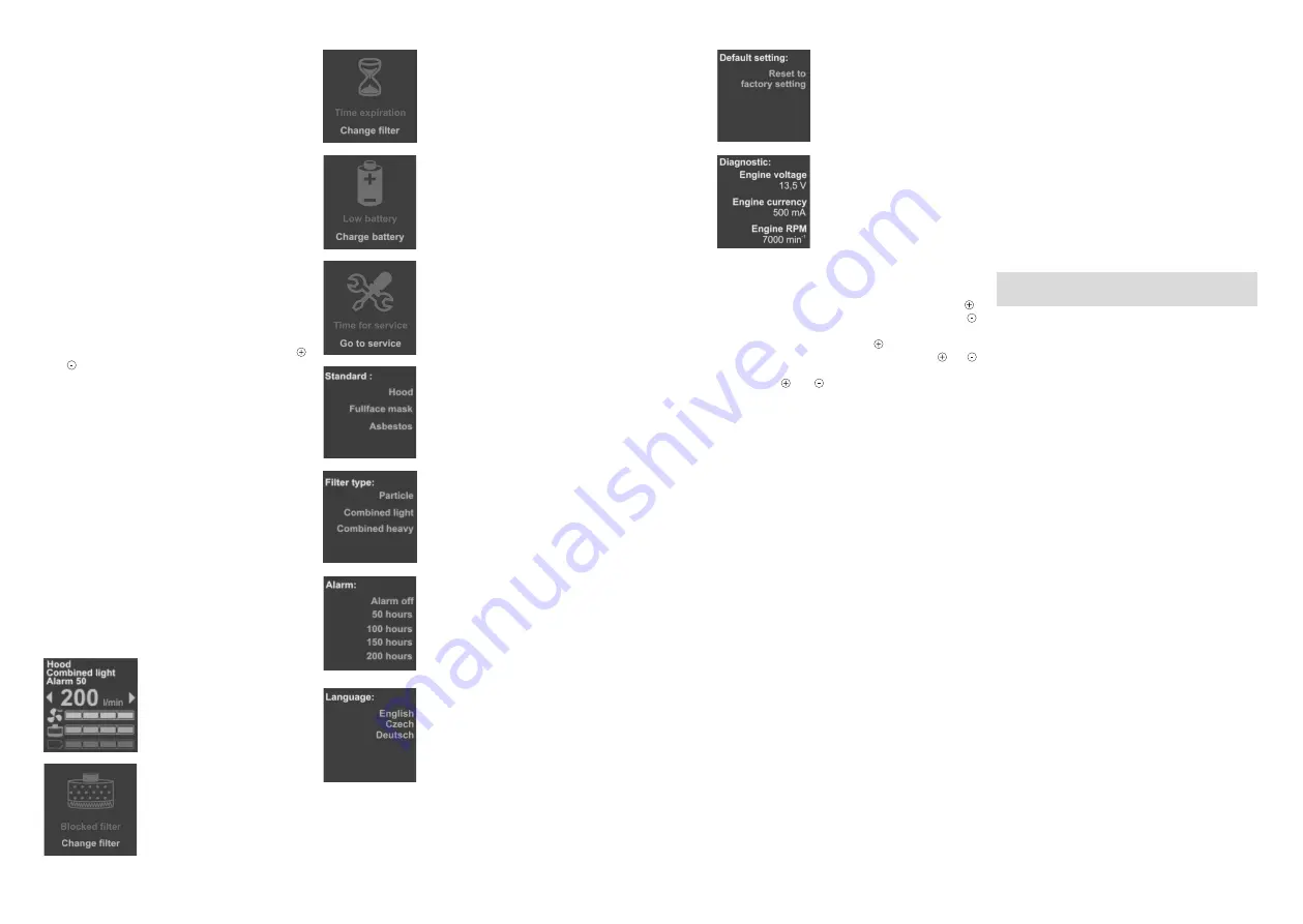
Monitoring panel
– displays
selected standard, type of filter
in use, remaining and set alarm
time, present flow volume, the
present state of filter clogging and
battery charging.
Alarm
– alarm informing the
user about unsatisfactory air-flow
through the unit due to filter clo
-
gging. It is vital to leave the conta-
minated area and replace filters.
Alarm
– alarm notifying the user
of the filter expiry which can be
pre-set. The alarm is also repre-
-sented by a red LED located
next to the display.
Alarm
– alarm notifying the user
of battery discharge. It is vital to
leave the contaminated area and
replace or recharge the battery.
Alarm
– alarm notifying the user
of time for service. It is necessary
to contact your supplier for regu-
lar service.
Standard selection for the unit.
EN 12 941 – is for hoods,shields
and helmets.
EN 12 942 – is for masks and
half-masks.
Filter type being used at present.
If the incorrect type of filter is set,
the filter clogging control does not
work correctly.
Setting the useful life of filters.
This function enables to watch
the life of the filters beginning at
the moment of setting the value.
This alarm is useful, for example,
if there is a time limit for using a
filter; e.g for mercury filters it is
only 50 hours.
Language setting- enables to set
the language of the MENU.
This function resets all specifi
-
cations of the unit to the initial
factory configuration.
Displays functional specifications
of the unit, mainly for diagnos
-
tics purposes of possible faults
during service.
Using the MENU for unit 3F Plus
MENU access– press both buttons at the same time for
2 seconds after switching the unit on.
• Movement to particular items of the MENU - button .
•
Item selection from particular MENU offers - button
.
•
Confirmation of your selection from particular Menu
offers – long press on button
.
• Leaving the MENU – long press of both buttons and .
• Turning the display orientation by 90° – short press
of buttons and .
4. Before usage
4.1. Control procedure before each usage
Make sure that:
• All components are all right without any visible vio-
lence or damage (above all there must not be any
cracks, holes, leakage).
• Replace any damaged and worn-down parts. Be
particular about the good state of the air supply hose
and of the sealing components
• The hose is connected correctly to the powered re-
spiratory unit as well as to the headtop; after swit-
ching the powered respiratory unit on, air is brought
into the headtop; the air-flow in the hose is sufficient
(Point 4.2.)
•
Charge the battery before using it for the first time,
see Point 6.2.
4.2. Air-flow test
Disconnect the air hose.
•
Screw the air flow meter into the output thread of
the unit; then hold the unit in upright position at eye-
-level.
•
Switch the filter unit on. The flow amount is satis
-
factory if the flow meter float is in the green field. If
it is in the red field (see picture attachment), the unit
must be inspected (see Chapter 7).
5. Maintainance and cleaning
• Always clean your CleanAIR
®
unit after finnishing
work. Check all parts by detail and replace damaged
parts.
• Cleaning must be done in a well ventilated room.
Beware of breathing in harmful dust settled on indi-
vidual parts of the filter unit and accessories!
• Do not use cleaning agents with solvents or abra-
sive cleaners in any case.
•
The outer surface of the filter unit can be cleaned
with soft fabric moistened in solution of water and
usual washing-up liquid. After cleaning dry individual
parts properly.
•
Do not allow water or other liquid to get into the filter
unit!
• The air hose can be washed out with clean water
after disconnection from the unit.
6. Spare parts replacement
CA Chemical 3F
There are three filters attached to the unit with thread
RD40x1/7“. The vital rule is to use a set of three filters
of the same type at a time!
Install only new filters without any damage.
It is forbidden to clean a filter or blow through it in
any way!
From the hygiene point of view it is recommended not
to leave a filter in the unit for more than 180 working
hours! It is also possible to use a pre-filter which holds
larger particles and especially aerosols which can stick
up the filter during paint-spraying and thus it prolongs
the life time of the filter.
Replacement of filters CA Chemical 3F
see Picture appendix no.2
Picture 2A :
Demounting is done by unscrewing each filter sepa
-
-rately anticlockwise.
Caution!
Before mounting new filters, make sure the
new filters are undamaged, in the original pac-king and
their service life is not expired (expiry is marked directly
on the body of the filter). Check also whether the seals
at the connecting points of the filters and the filter unit
are unfaulted and safe.
Picture 2B :
New filters are mounted one by one clockwise. It is ne
-
cessary to be particular about screwing them tight to
ensure tightness of the joints.
6.2. Batteries
Important! Batteries are delivered uncharged. Each
time before using a battery for the first time charge it.
The battery charger is not made for outdoor service. It
can be used only in premises protected against rain
and moisture. Never charge the battery in potentcially
explosive atmosphere. It is forbidden to use the batte-
ry charger for other purposes than those determined
by the producer. Charging starts after connecting the
charger to the power supply and the battery. As soon
as the battery is fully charged, the charger will switch
over to maintainance cycle and the battery stays fully
charged all the time. The charging time is 3-4 hours.
6.2.1. Battery charging
1. Check that the mains voltage is right for the
battery charger.
2. Connect the charger to the mains.
3. Connect the charger to the charging connector
located at the back of the battery. The charging
Summary of Contents for CHEMICAL 3F Plus
Page 33: ...64 65...


