4
the plate out.
• insert the new protection plate into the
grooves on sides of ADF filter opening by
bending it slightly..
CleanAIR® Verus WELDING HELMET AND HEAD-
GEAR adjustment
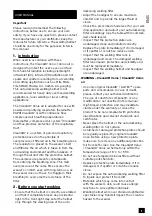
Headgear adjustment (*PICTURE 5, 6, 8)
The size of the headgear (head circumference)
can be adjusted by turning the rear wheel in
order to fit any head size. The depth of the
headgear can be adjusted by repositioning the
four vertical head straps. To release the head
straps from the headgear, just pull the straps
out of the pin-locks. Snap the head straps on the
pin-locks when reaching the optimal position.
Headgear replacement
For headgear replacement press the black tabs
on the top of the pivot point while sliding the
headgear forward.
To insert the new headgear slide the rails into
the groove on the pivot point. Both sides must
be equally positioned.
Tilt (vertical viewing angle) adjustment
(*PICTURE 8)
Tilt can be adjusted on the left side of the
helmet by turning the tilt adjustment knob.
Turning the knob clockwise will tilt the helmet
downward, while turning counter-clokwise will tilt
the helmet upward.
Distance Adjustment (*PICTURE 6)
Adjusts the distance between the face and the
ADF by pressing the black tabs on the top of
the pivot point while sliding the helmet forward
or backward. Release the tabs when reaching
the optimal position. Both sides must be equally
positioned.
Air flow direction adjustment
The direction of the airflow to the lower part of
the helmet can be adjusted with the adjustment
lever outside the helmet (*PICTURE 11), while the
intensity can be adjusted with two sliders on the
inside of the helmet.
When both sliders are pushed up („-“) you
maximize the airflow that comes directly
towards your mouth.
When both sliders are pushed down („+“), the
side air ducts open and the airflow is diverted
to the sides, the airflow coming directly to your
mouth is reduced.
Direction of air flow supplied to the lower part of
the helmet can be adjusted by adjustment lever
outside the helmet.(*PICTURE 11)
Headgear mounting set replacement
(*PICTURE 7)
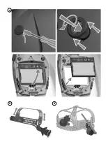
Unscrew both tension knobs on the sides of the
helmet and remove the mounting sets from the
welding helmet.
Place the new mounting sets in the welding
helmet with the square nut on both sides in the
round hole of the helmet.
Make sure you have placed the rack on the
pinion in the helmet. Screw the tension knobs on
both sides into the square nut of the mounting
sets and tighten them.
Secure with external screws to the square nut.
(PICTURE 8).
Storage and shelf life
Store the welding helmet in a dry and clean
place at room temperature, avoid direct sunlight
(temperature range from -10 °C to +55 °C
with relative humidity between 20 and 95 %).
Longterm storage in temperatures above 45 °C
can reduce the lifetime of the battery.
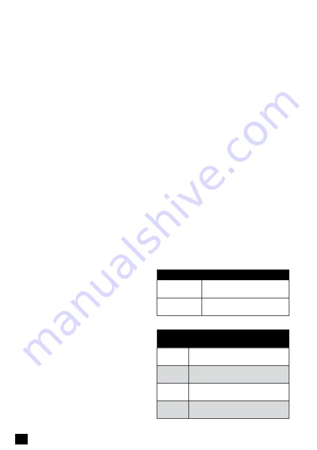
Product code
Product description
70 30 01
Welding helmet CleanAIR®
Verus air 5-8/9-14
40 30 01
Welding helmet CleanAIR®
Verus 5-8/9-14
Spare parts, accessories:
Product
code
Product description
40 30 97
40 30 97 Welding helmet CleanAIR® Verus w/o
headgear, w/o ADF
70 30 97 Welding helmet CleanAIR® Verus
air incl. headgear, w/o ADF
72 00 20 VariGEAR Airduct - headgear incl.
airduct
72 00 10
VariGEAR Comfort, headgear incl.
sweatband
ENG


