Installer's Manual: Clean Burn Air Compressors
3-14
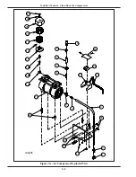
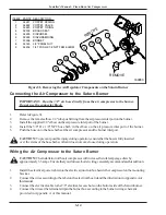
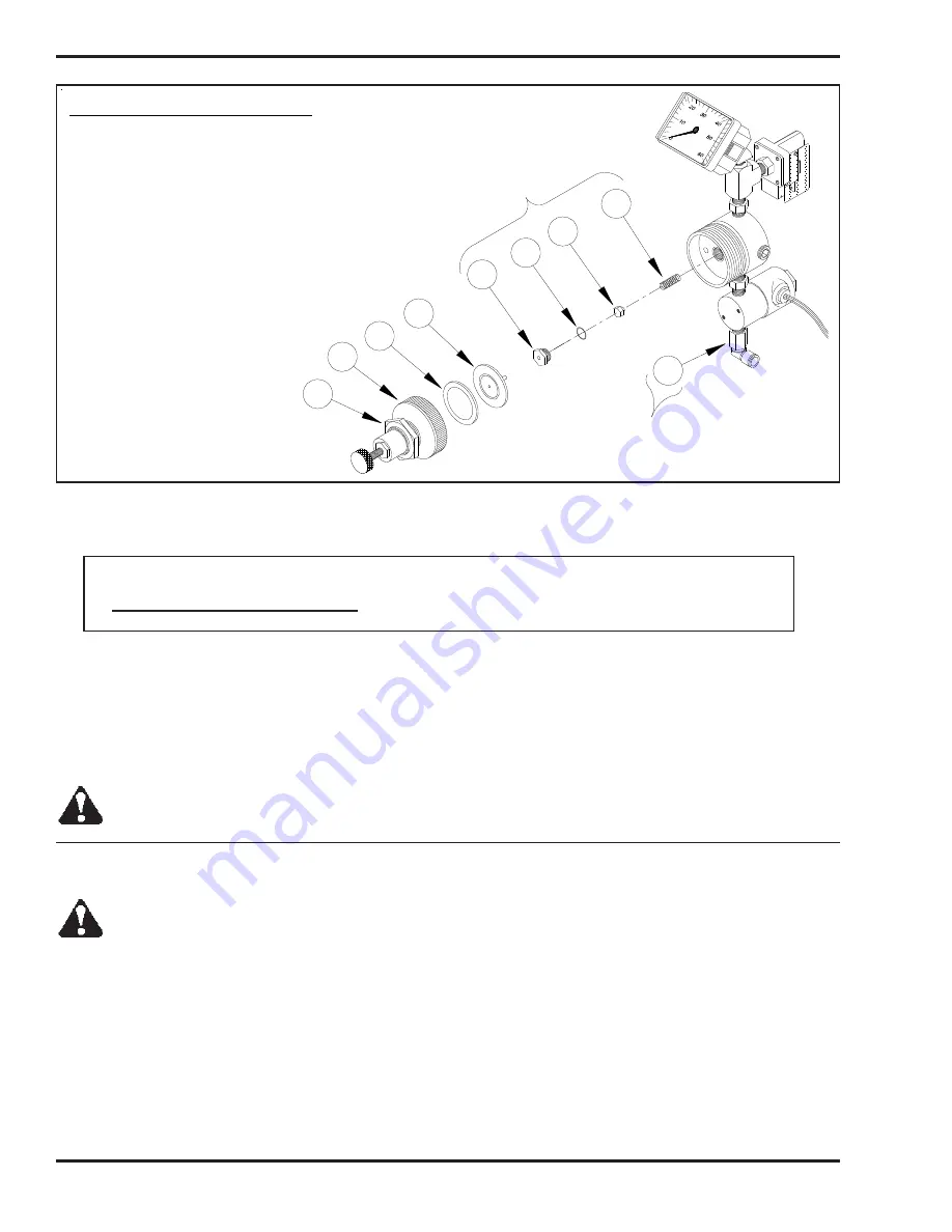
Figure 3I - Removing the Air Regulator Components on the Saturn Burner
1.
Refer to Figure 3I.
2.
Remove the female elbow 1/4" tube push fitting from the air pressure inlet port on the burner.
3.
Install the supplied 1/8" elbow on the air pressure inlet port of the burner.
4.
Install the 3/8" H x 1/8" NPT hose barb in the elbow on the air pressure inlet port of the burner.
5.
Push the hose onto the hose barbs at the air compressor and the burner inlet port.
CAUTION:
To prevent possible injury during operation, ensure that the hose is fully inserted
over the stems of the hose barbs so that it does not come loose during operation.
Connecting the Air Compressor to the Saturn Burner
CAUTION:
The installation of the air compressor will increase the total amperage draw by
approximately 3.5 amps. Ensure that your furnace/boiler wiring can safely accommodate this addition.
1.
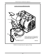
Install the electrical power cable into the electrical junction box beside the compressor on the mounting
bracket.
2.
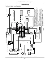
Connect the wires according to the label on the electrical box lid and the illustration in Appendix A of
this manual.
3.
Connect the electrical cable to the 7/8" electrical access hole on the bottom side of the Saturn burner.
4.
Connect the wires at the terminal strip in the burner box according to the burner wiring schematic
provided in Appendix A of this manual.
Wiring the Air Compressor to the Saturn Burner
IMPORTANT: Run the 3/8" air hose directly from the air compressor to the burner.
Do not use the connector block.
I89063
1
ITEM # PART# DESCRIPTION
1 32221 POPPET SPRING
2 32222 POPPET VALVE
3 32223 POPPET O−RING
4 32305 BRASS SEAT
5 32225 DIAPHRAM
6 32226 DIAPHRAM RING
7 33308 BONNET
8 34145 3/4" PANEL NUT
9 32202 1/4T PUSH X 1/8 NPT FEM ELBOW
2
5
6
7
8
3
4
RE
MO
VE
9
REMOVE
Summary of Contents for 14336
Page 2: ......
Page 6: ......
Page 8: ......
Page 12: ...Installer s Manual Clean Burn Air Compressors 2 2...
Page 32: ...Installer s Manual Clean Burn Air Compressors A 4...

