background image

SPECIAL BULLETIN

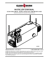
Clean Burn Model #14336 is a double-piston air compressor which can be installed on ALL Clean
Burn furnace and boiler models.

IMPORTANT INFORMATION CONCERNING THE SERVICE RATING

OF THE AIR COMPRESSOR

Air compressor model #14336 has a service rating of approximately 75%.  This means that the air compressor
can operate continuously for approximately 45 minutes (75% of one hour), and then it must not operate for
approximately 15 minutes (25% of one hour) to allow the air compressor to "cool down."  This works well for
most furnace/boiler installations where the unit will cycle on and off a few times during an hour.

CAUTION:


If the furnace/boiler will run continuously (without cycling on and off a few times

during an hour), you must use an air compressor with a tank.

  (Refer to the air compressor specifications

for your furnace/boiler when purchasing an air compressor with a tank.)  

DO NOT use air compressor model

#14336 if your furnace/boiler will run continuously for periods which exceed the 75% service rating.

This will overheat the air compressor and severely damage the teflon rings and teflon skirt in the air compressor,
resulting in poor air pressure output from the compressor.

IMPORTANT INFORMATION CONCERNING ADJUSTMENT

OF THE AIR COMPRESSOR

It is very important to follow the instructions 

"Adjusting the Air Compressor During Operation"

 in this

manual.  This procedure involves the adjustment of the pressure relief on the air compressor so that the precise
air pressure (12 to 18 psi) required for proper burner operation is provided to the burner.  Excess air pressure
is bled off through the pressure relief.

CAUTION: 

 DO NOT run the air compressor without properly adjusting the pressure relief.  This will overheat

the air compressor and severely damage the teflon rings and teflon skirt in the air compressor, resulting in poor
air pressure output from the compressor.

IMPORTANT INFORMATION CONCERNING YOUR

AIR COMPRESSOR MODEL

Summary of Contents for 14336

Page 1: ...NSTALLATIONS Allinstallationsmustbemadeinaccordancewithstateandlocalcodeswhich maydifferfromtheinformationprovidedinthismanual Savetheseinstructionsforreference IMPORTANTFORCANADIANINSTALLATIONS Thein...

Page 2: ......

Page 3: ...or costs of removal or reinstallation of its products and shall not be liable for transportation costs to and from its plant at Leola Pennsylvania Use of parts for modification or repair of the produ...

Page 4: ...the registered trademarks or trademarks of their respective owners COPYRIGHT Copyright 2010 Clean Burn Inc All rights reserved No part of this publication may be reproduced or distributed without the...

Page 5: ...3 5 Preparing the Furnace Cabinet CB 1750 CB 2500 CB 3250 3 7 MountingtheAirCompressor CB 1750 CB 2500 CB 3250 3 7 PreparingtheFurnaceCabinet CB 3500 CB 5000 3 9 MountingtheAirCompressor CB 3500 CB 5...

Page 6: ......

Page 7: ...rwhenpurchasinganaircompressorwithatank DONOTuseaircompressormodel 14336 if your furnace boiler will run continuously for periods which exceed the 75 service rating Thiswilloverheattheaircompressorand...

Page 8: ......

Page 9: ...tact your Clean Burn dealer before starting any of the procedures in this manual Following is an outline of the air compressor installation process UNPACKING INSTALLINGTHEAIRCOMPRESSOR InstallingtheAi...

Page 10: ...e boiler For your safety Clean Burn documentation contains the following types of safety statements listed here in order of increasing intensity NOTE A clarification of previous information or additio...

Page 11: ...Immediately notify the freight company and your Clean Burn dealer in case of shipping damage or shortage s Keep all components together so you will have them as needed for assembly and installation F...

Page 12: ...Installer s Manual Clean Burn Air Compressors 2 2...

Page 13: ...ionofmounting stabilizerbrackets 2 InstallationofAirCompressoronFurnace Boiler 3 InstallationofFurnace Boiler includingoilpump wiring oil airlines stack thermostat KeeptheFurnace BoilerOperator sManua...

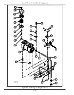
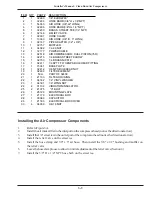
Page 14: ...Installer s Manual Clean Burn Air Compressors 3 2 Figure3A AirCompressorExplodedView I89055 30 1 4 10 25 12 6 8 7 9 2 3 11 24 26 28 27 29 17 14 16 15 22 18 19 20 21 23 13 5...

Page 15: ...09 FILTER ELEMENT 20 1 N A PART OF 32409 21 1 21130 FILTER HOUSING 22 1 34182 1 4 VINYL WASHER 23 1 34181 1 4 WING NUT 24 4 31104 VIBRATION INSULATOR 25 2 21075 U BOLT 26 1 25120 MOUNTING PLATE 1 29 1...

Page 16: ...Installer s Manual Clean Burn Air Compressors 3 4 Figure 3B Air Compressor Installed on the Saturn 140 Saturn 240 I89060...

Page 17: ...ylocktheall threadrodsinposition Mounting the Air Compressor Furnace Models Saturn 140 240 CAUTION Thecompressormustbesecurelymountedasdescribedinthissection Ensurethat all nuts and bolts are firmly t...

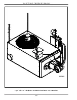
Page 18: ...Installer s Manual Clean Burn Air Compressors 3 6 Figure 3C Air Compressor Installed on the CB 1750 CB 2500 CB 3250 I89056...

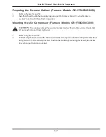
Page 19: ...all thread rods in position Mounting the Air Compressor Furnace Models CB 1750 2500 3250 CAUTION Thecompressormustbesecurelymountedasdescribedinthissection Ensurethat all nuts and bolts are firmly tig...

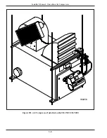
Page 20: ...Installer s Manual Clean Burn Air Compressors 3 8 Figure 3D Air Compressor Installed on the CB 3500 CB 5000 I89058...

Page 21: ...e of the forward all thread rods as illustrated inFigure3D Mounting the Air Compressor Furnace Models CB 3500 and CB 5000 CAUTION Thecompressormustbesecurelymountedasdescribedinthissection Ensurethat...

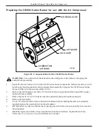
Page 22: ...heaircompressorassembly 14336 2 Removetheself tappingscrewwitha1 4 nutdriverandswingopenthedouble hingedlidtoexpose theheaterblockassembly 3 RefertoFigure3F Usea1 8 Allenwrenchtoloosenthelockingbolton...

Page 23: ...e CB 500 Series Burner Preparing the CB 500 Series Burner for use with the Air Compressor continued 3 2 1 7 6 5 4 8 1 0 9 REMOVE THESE PARTS STEP 2 INSTALL STEP 1 SAVE AND USE THESE 4 SCREWS AND WASHE...

Page 24: ...ltheelectricalpowercableintotheelectricaljunctionboxbesidethecompressoronthemounting bracket 3 ConnectthewiresaccordingtothelabelontheelectricalboxlidandtheillustrationinAppendixAof thismanual 4 Conne...

Page 25: ...eself tappingscrewswitha1 4 nutdriverandopentheelectricalboxcovertoexpose theairregulatorassembly 3 RefertoFigure3I Loosenthe3 4 nutontheairregulatorbonnetandslidetheairregulatorassembly outoftheelect...

Page 26: ...approximately3 5amps Ensurethatyourfurnace boilerwiringcansafelyaccommodatethisaddition 1 Installtheelectricalpowercableintotheelectricaljunctionboxbesidethecompressoronthemounting bracket 2 Connectth...

Page 27: ...essor 1 Refertoyourheatingequipment sOperator s Manual Section6 BurnerStartUpand Adjustment Note the proper air pressure setting e g CB 2500furnacerequiresanair pressuresettingof12 18psi 2 Followthedi...

Page 28: ...the air intake filter element at least monthly according to the manufacturer s instructions included with the filter 2 Replace the air intake filter element annually ATTENTION DO NOT operate the air...

Page 29: ...R WHITE BLUE AIR OPTIONAL COMPRESSOR BLOCK HEATER 400 WATTS BLACK BLACK RED BLACK WALL THERMO STAT NOTE WHEN RELEASING OR INSTALLING WIRES ON THE TERMINAL STRIP USE THE SMALL SCREWDRIVER SUPPLIED WITH...

Page 30: ...MP GREY SWITCH FORMER BLUE TRANS WHITE AIR N O BLACK ORANGE BLACK BLACK SOLENOID BLACK AIR RED PUR BURNER MOTOR WHITE GRN BK WHITE G 1 2 4 3 TO BURNER HI LIMIT SWITCH OIL SOLENOID SWITCH PROVING BLACK...

Page 31: ...ONDUIT ORANGE WIRENUTS BROWN WHITE TO TERMINAL BLOCK INSIDE BLUE CAPACITOR WHITE BLUE CONNECT ONE END OF THE GROUND WIRE TO THE GROUND SCREW ON THE COMPRESSOR AND THE OTHER END TO THE SCREW ON THE OUT...

Page 32: ...Installer s Manual Clean Burn Air Compressors A 4...

Reviews: