15
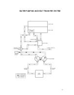
Water Pumping and Heat Transfer System:
Cold water enters the panel through the water
inlet. When the water tank is full the valve will
automatically shut off.
Water then flows from the water tank, through a
strainer, into the water pump where chemical is
introduced at this point. Then it is pumped to the
pressure regulator that provides and maintains the
desired pressure setting.
A certain amount of water is by-passed from the
pressure regulator due to over pumping capacity
of the water pump. Water that is not called for in
the cleaning process is channeled to the by-pass
coil in the recovery tank then flows to the inlet side
of the pump to be circulated again.
The heating stage occurs when the water leaving
the pressure regulator and directed to the first of
two heat exchangers. Heat from the vehicle
engine coolant is exchanged to the cleaning
solution spiraled copper tubing. This allows the
engine coolant to travel in a counter rotating
direction to the cleaning water during the
exchange process creating a very efficient transfer
of heat out of the engine and into the cleaning
solution.
The hot solution then exits the second heat
exchanger where it enters the outlet manifold.
The manifold serves as a sensing point and
connection for the high-pressure hoses.
Finally, the cleaning solution then passes through
pressure hoses and is distributed by the cleaning
tool to a surface that is being cleaned, completing
the water pumping and heating cycle of the
cleaning unit.
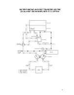
Optional P.T.I.
With the Optional Post Thermal Increase, the
cleaning solution goes to a second stage of
plumbing and heating which takes place in the
heater core located just after the vacuum pump.
This is the hottest point of exhaust air coming from
the vacuum pump. The hot exhaust air is forced
through the post heat core, creating the second
stage of heat transfer to the cleaning solution.
Required Maintenance of P.T.I.
Annual inspection of the fins inside the P.T.I. is a
requirement do to the potential folding over of the
fins or build up of debris, lint, dirt etc. This will
cause excessive stress on the drive line including
the blower, PTO shaft and PTO clutch. The blower
must be removed to see the possible results of the
wear and tear on the fins. Cleanco would
recommend this procedure be done by a Qualified
Service Center.
Heat Max P.T.I Operating Instructions:
Overview
The “Heat Max P.T.I.” is designed to transfer the
exhaust heat generated by the vacuum blower, to
the cleaning solution as the final heating stage. To
fully understand the heat transfer system of the
Cleanco Compact the following steps occur.
Before the P.T.I. will efficiently transfer heat to the
cleaning solution, the blower must be brought up
to temperature. This is accomplished when the
vehicle coolant system is first brought up to
operating temperature either through idling or
driving to the job site. Then the unit must be
turned on to high idle with the vacuum port of the
recovery tank closed off with the plug on the inlet
barb. The operating temperature of the P.T.I. will
be available in about ten minutes of running unit.
The P.T.I. will take much longer to reach operating
temperature if this procedure is not done and in
fact will cool the water until the blower can reach
the desired transfer heat rate.
Step 1
The water flows from the fresh water tank through
a strainer, into the water pump where it is pumped
to the pressure regulator providing constant
desired pressure.
Step 2
The next stage of water flow is to the heat
exchangers (Dual or Quad), when water is called
for in the cleaning process, it flows to the heat
exchangers under pressure. Heat from the engine
coolant is exchanged to the cleaning solution
through a series of spiraled copper tubing. This
allows the engine coolant to travel in a “reverse
flow” direction to the cleaning solution creating a
very efficient transfer of heat out of the engine and
into the cleaning solution.
Step 3
The last stage of the heat exchange takes place in
the “Heat Max P.T.I.” located under the baseplate.
This is the hottest point of the exhaust from the
vacuum blower which is forced through th
e “Heat
Max P.T.I.”. The cleaning solution travels from the
Summary of Contents for Compact 45
Page 1: ...VERSION AUG 2017...
Page 13: ...12...
Page 14: ...13...
Page 18: ...17 WATER PUMPING AND HEAT TRANSFER SYSTEM...
Page 19: ...18 WATER PUMPING AND HEAT TRANSFER SYSTEM DUAL HEAT EXCHANGER WITH P T I OPTION...
Page 28: ...27 CLEANCO COMPACT OVERHEAD VIEW...
Page 29: ...28...
Page 30: ...29 FRONT PANEL 45 47 FRONT VIEW...
Page 31: ...30 FRONT PANEL 45 47 BACK VIEW...
Page 33: ...32 FRONT PANEL PLUMBING P 1...
Page 34: ...33 FRONT PANEL PLUMBING P 2...
Page 37: ...36 COMPACT RECOVERY TANK...
Page 39: ...38 COMPACT BASEPLATE 45 47 P 1...
Page 40: ...39 COMPACT BASEPLATE 45 47 P 2...
Page 45: ...44 KIT INSTALLATION 45 47 P 1...
Page 46: ...45 KIT INSTALLATION 45 47 P 2...
Page 49: ...48 DUAL HEAT EXCHANGER...
Page 51: ...50 P T I...
Page 53: ...52 COVER HOLDER KIT...
Page 55: ...54 PTO SHAFT...
Page 58: ...57 C A D EXTERNAL OPTION PAGE 1...
Page 59: ...58 C A D EXTERNAL OPTION PAGE 2...
Page 61: ...60 F W TANK AQUA STORAGE 120 GALLON...
Page 63: ...62 F W TANK AQUA REEL TANK 125 GAL P 1...
Page 64: ...63 F W TANK AQUA REEL TANK 125 GAL P 2...
Page 75: ...74 CLEANCO COMPACT ELECTRIC WIRING P 1...
Page 76: ...75 CLEANCO COMPACT ELECTRIC WIRING P 2...
Page 77: ...76...
Page 78: ...77...
Page 79: ...78...
Page 80: ...79...
Page 81: ...80...
Page 82: ...81...
Page 83: ...82...
Page 84: ...83...


