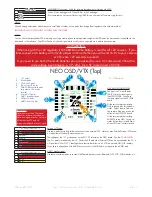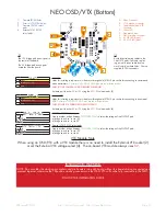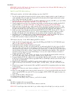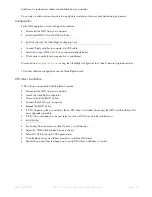
Failure to adhere to these warnings will void your warranty and destroy your hardware.
• Observe polarity at ALL TIMES.
Check
and
DOUBLE CHECK
before applying power. Do not rely on wire color-cod-
ing alone.
• Perform a continuity test between B and Battery - terminals on the FC before powering up for the first time.
A short circuit can start a FIRE!
• POWER OFF
before unplugging, plugging in or making any connections.
• Connect only 3S or 4S LiPo batteries to the FC/PDB. (4.2v per cell).
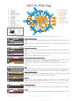
• Ensure the 3S/12V selection jumper is set correctly. If all three pads are bridged your board and attached equip-
ment will be destroyed - only connect the center pad SQUARE to a single TRIANGLE pad..
• Ensure the two 5V/12V selections jumpers are set correctly for your VTX and Camera. If all three pads are bridged
your board and attached equipment will be destroyed - only connect the center pad SQUARE to a single TRIANGLE
pad.
• Do not connect any other SOURCES of power to the NEO other than the a battery via the XT60/Battery pads and/
or a USB cable.
• Do not connect a LiPo to any where other than the XT60/B/- pads.
• Do not connect GND,
5v
,
VIN,
or
3.3v
to each other (short circuit).
• Do not connect GND,
5v
,
VIN,
or
3.3v
to any inputs or outputs unless specifically stated.
• Do not connect any input or output to any other input or output unless specifically stated.
• Always align USB plug and socket when inserting/removing USB cables to prevent damage to the USB socket.
• Always use a current limiter when powering on for the first time - this can help save your equipment in case you
wired something incorrectly. (This applies to all builds, not just with this product!).
WARNINGS
GENERAL ADVICE
Follow the advice below for best performance and long-life of your product:
• Apply resin/glue to reinforce JST-SH connectors - helps if you crash your aircraft.
• To further protect the board from crashes you can add a some additional solder to the edges of the JST-SH and USB
sockets to reinforce them.
• Support JST connector sockets when inserting/removing cables.
• Ensure all wires are tinned correctly, make sure there are NO loose strands of multi-core cable sticking out - This is
VERY IMPORTANT FOR THE BATTERY CONNECTIONS.
• Ensure the board is the right way up when soldering the header pins and sockets. Once header pins or sockets are
installed they can only be removed by a soldering professional.
• For optimum performance do everything you can to prevent vibrations reaching the accelerometer/gyro sensor.
e.g. balance motors, props use rubber isolation grommets if required and secure everything - no loose cables/etc.
IMPORTANT:
• Use a high quality soldering iron and good solder.
• Tin/Lead solder is
MUCH
easier to use than other Lead-free solder.
• Use solder with flux and remove any flux residue after soldering. AVOID CORROSIVE FLUX!
• Check for and remove any solder balls that you may have created when soldering - use a magnifying glass.
• Ensure you have sufficient fume extraction when soldering.
• Pin headers that connect to the GND signal will be more difficult to solder because the PCB will sink the heat from
your soldering iron. Solder the other pins near to the GND pin first, then the GND pin - by the time you get to the
GND pins you will have heated the board and it will be easier to solder them.
• If you have never soldered before then DO NOT attempt to solder the OSD, practice on something else first. Get
some VeroBoard and some single-core wire from Maplin/RadioShack/etc and practive on that.
• Once you have soldered pin headers in place
DO NOT
attempt to remove them unless you are
highly skilled
in
de-soldering and have the correct tools. Overheating the board or components will destroy it.
SOLDERING
SPRacingF3NEO
http://seriouslypro.com - http://cleanflight.com
Page 4


