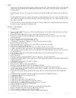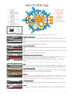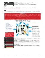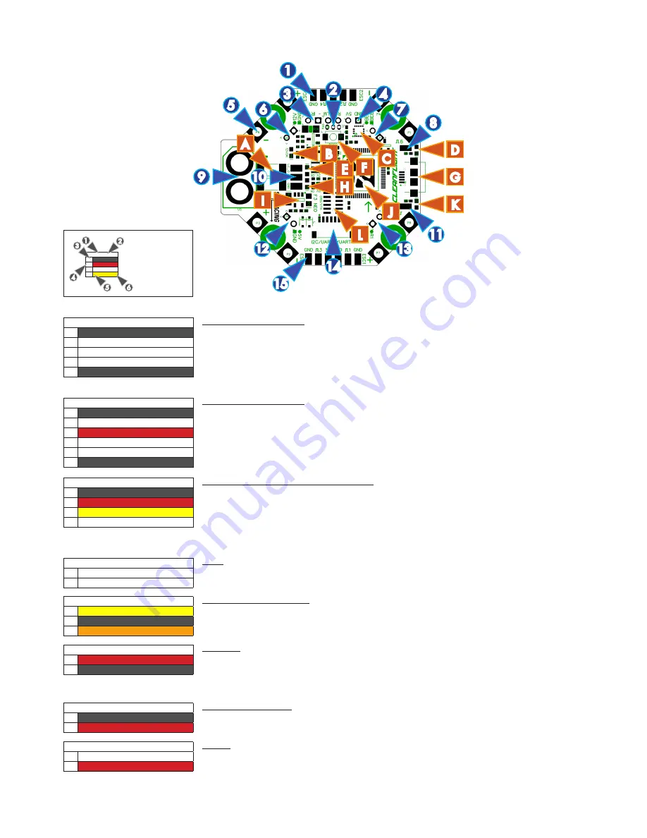
NEO FC/PDB (Top)
1. Front pads
2. Spek Sat pads.
3. IR pads.
4. UART2/RX/TLM pads.
5. ESC power pads (8x).
6. 12V pads.
7. Buzzer pads.
8. XT60 pads
9. ESC 6 pad.
10. LC Filter and 5V outputs.
11. ESC 5 pad.
12. 5V pads.
13. UART1 pads.
14. I2C UART3/UART5 pads.
15. Rear pads.
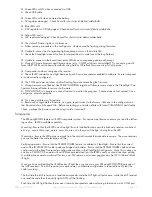
10
SPRacingF3NEO
http://seriouslypro.com - http://cleanflight.com
Page 5
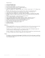
Table Legend
1. Port name
2. Port number
3. PCB marker / Pad
shape
4. Pin number
5. Signal Name
6. Signal Color
UART2
(2)
1
l
GND
2
VIN
3
TXD/SWDCLK
4
RXD
3
5
1
6
2
4
A. Current sense resistors.
B. 12V OK LED (Amber).
C. ACC/GYRO sensor.
D. STATUS1 LED (Red).
E. 3.3V OK LED (Blue).
F. BOOT button.
G. MicroUSB socket.
H. 5V OK LED (Green).
I.
3.3V Regulator.
J.
STM F3 CPU.
K. STATUS2 LED (White)
L. 12pin stacking connector.
12
5
9
BUZZER
(7)
1
n
BUZZER- (B-)
2
l
(B+) / 5v
BUZZER
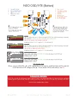
For connecting to an active buzzer OR the BUZZER headers pins on the OSD/VTX directly above the NEO.
IR LED
(3)
1
n
IR -
2
l
IR +
IR LED
IR + (Pin 2, ROUND) is used to connect an IR LED - either direct-solder the LED or attach the LED via a cable.
The LONG leg of the LED goes in the ROUND hole. The SHORT leg of the LED goes in the SQUARE hole.
13
1
4
7
C
A
15
6
14
I
J
B
E
H
L
3
2
11
8
D
G
K
When stacking the OSD/VTX board solder the supplied VERY LOW PROFILE SOCKETS into 6/7/12/13.
ESC Power
(5)
1
n
ESC POSITIVE
2
n
ESC GND
ESC Power
2 pads per corner. Use a pair of cables for each ESC. Connect ESC GND from NEO to BATTERY - on ESC.
Connect
ESC POSITIVE
from NEO to
B
on ESC.
Pay attention to the +/- symbols next to the pads.
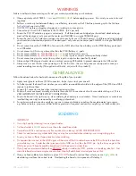
DO NOT ACCIDENTALLY BRIDGE ANY OF THE ESC OR BATTERY PADS WHILE SOLDERING - CHECK!
UART2/PPM
(4)
1
n
GND
2
l
5v
3
l
RXD (R2 / PPM)
4
l
TXD (T2 / TLM)
UART2/PPM - Serial RX or PPM RX + Telememetry
Use a standard 3 pin cable on pins 1-3 to attach to either a Serial RX receiver or a PPM receiver. Use pin 4
as telemetry output when using PPM.
5v
is also supplied when connecting via USB.
Note: When using a Serial RX receiver the TXD (T2) pin cannot be used for telemetry. Use UART5 TXD
instead.
NOTE: There is a recevier connector on the bottom of the board which you may find easier to use.
ESC2/4 & RSSI
(1)
1
n
ESC 4 GND
2
n
ESC 4 SIGNAL
3
n
RSSI (PWM)
4
n
ESC 2 SIGNAL
5
n
ESC 2 GND
Front Pads / ESC 2/4 & RSSI
Use pads 1 & 2 and the two ESC power pads either side of the front left mounting hole to connect 4 wires to
ESC 4.
Use pads 5 & 4 and the two ESC power pads either side of the front right mounting hole to connect 4 wires to
ESC 2.
If your receiver has a PWM RSSI signal connect it to pad 3.
ESC 1/3 & LED STRIP
(15)
1
n
ESC 3 GND
2
n
ESC 3 SIGNAL
3
n
5v
3
n
LED STRIP
4
n
ESC 1 SIGNAL
5
n
ESC 1 GND
Front Pads / ESC 2/4 & RSSI
Use pads 1 & 2 and the two ESC power pads either side of the front left mounting hole to connect 4 wires to
ESC 4.
Use pads 5 & 4 and the two ESC power pads either side of the front right mounting hole to connect 4 wires to
ESC 2.
If your receiver has a PWM RSSI signal connect it to pad 3.
Spektrum Satellite
(2)
1
l
RXD (R3)
2
l
GND
3
l
3.3v
Spektrum Satellite socket holes.
Holes ready to install a top-mount or side-mount through hole JST-ZH 3 pin socket for connecting to a Spektrum
Satellite receiver - UART3. PIN 1 faces towards the bottom of the board.
F
12V POWER-to-OSD/VTX
(6)
1
n
GND
2
l
12V*
12V POWER-to-OSD/VTX
For connecting to the GND and 12V* pins on the OSD/VTX directly above the NEO. *See 12V/3S selector.


