SPRacingF3NEO
http://seriouslypro.com - http://cleanflight.com
Page 6
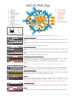
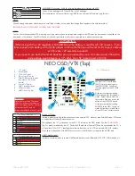
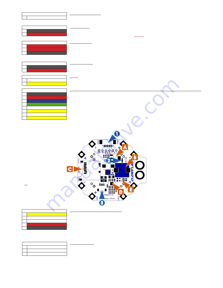
NEO FC/PDB (Bottom)
1. Receiver port.
2. 3S/12V selector.
3. SWD socket.
A. 12V regulator.
B. LC Filter (25V MAX)
C. Micro SD socket.
D. 5V regulator.
E. Current sensor.
TIP
The 3S bridge pad arrows point to
the center of the board.
The 12V bridge pad arrows point
outwards from the board.
3S/4S SELECT
(2)
1
t
3S
2
n
OUTPUT
3
u
4S
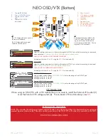
3S/12V Select Pads
Create a solder bridge between
TWO PADS ONLY
to select the voltage of the OUTPUT pad.
a) bridge
t
and
n
to use 3S - 12V voltage regulator
DISABLED
.
All 12V sources supplied at battery volt-
age.
b) bridge
n
and
u
to use 4S - 12V regulator
ENABLED
.
5V POWER-to-OSD
(12)
1
n
GND
2
l
5V
5V POWER-to-OSD
For connecting to the GND and 5V pins on the OSD/VTX directly above the NEO.
ESC 5, ESC 6
(8,11))
1
n
ESC/SERVO signal
ESC/SERVO 5/6 SIGNAL
Additional ESC outputs, primarily used for PAN/TILT servos for tracking cameras. ESC 5/6 do not support
DSHOT.
BATTERY / XT60
(9)
1
l
BATTERY NEGATIVE - (towards rear)
2
l
BATTERY PO (towards front)
BATTERY / XT60
For connecting directly to a battery. Install an XT60 connector facing up or down OR use wires.
DOUBLE-CHECK XT60 CONNECTOR ORIENTATION BEFORE SOLDERING!
UART1-to-OSD
(13)
1
n
TXD (T1)
2
l
RXD (R1)
UART1
For connecting to the USART headers on the OSD/VTX directly above the NEO.
LC FILTER/5V OUT
(10)
1
n
LC FILTER (towards front)
2
n
5V
3
n
GND (towards rear)
LC FILTER/5V OUT
3 convenient pads for connecting external devices.
The LC filter output is at BATTERY voltage. See 12V/3S selector. Current drawn here is measured by the
amperage meter.
I2C/UART3/UART4 socket
(14)
1
l
GND
2
5v
3
SCL
4
SDA
5
TXD (T3)
6
RXD (R3)
7
TXD (T4)
8
RXD (R4)
I2C/UART3/UART4 socket
Use this socket to connect a GPS receiver with I2C MAG and optional BARO sensors to use Cleanflight GPS
features.
IMPORTANT: The
SCL
and
SDA
are
3.3v
signals
5.0v
is also supplied when powering via USB.
IMPORTANT:
5.0v
to
3.3v
logic level converters are
REQUIRED
for
SCL
/
SDA
if your sensors use
5.0v
signals.
IMPORTANT:
3.3v
ONLY signals
for UART3 R3/T3, UART4 can use
5.0v
signals (T4/R4).
RECEIVER
(1)
1
l
RXD (R2 / PPM)
2
TXD (T2 / FrSky TLM)
3
TXD (T5 / SmartPort/Hott TLM)
4
5v
5
GND
RECEIVER port - Molex Picoblade connector
Connect to a receiver using either of the two supplied cables.
FrSky XSR - Use Straight though cable. UART2 for Serial RX, UART5 for SmartPort.
Other Serial RX - Use dupont cable. UART2 for Serial RX, T5/UART5 for Telemetry (Hott/Smartport/etc).
PPM RX - Use dupont cable. RXD/R2/PPM for PPM, TXD/T2/UART2 for Telemetry.
NOTE: There are also header pins and holes for other receivers. UART5 T5 is ONLY on the receiver port.
5.0v
is also supplied when powering via USB.
1
2
3
C
B
E
D
A


