NOTE:
You can check the transponder LED is working by using a mobile phone camera pointed straight at the LED when the transponder is enabled via the
board and in the software. The LED will pulse an infrared signal which usually shows up purple via a mobile phone camera.
SPRacingF3NEO
http://seriouslypro.com - http://cleanflight.com
Page 7
NOTE:
When bridging select pads with solder, put a small blob of solder on two pads, then bridge them together with a little more solder.
IMPORTANT: DO NOT CONNECT ALL THREE PADS TOGETHER.
3S WARNING
When using 3S the 12V regulator is DISABLED and the battery is used for all 12V sources. If you
later connect a 4S battery with 3S/4S jumper in 3S mode then you will send 16.8v to your camera
or VTX when 12V selectors are used!
If you need to use both 3S and 4S batteries you are advised to use a 5V camera and VTX with a
wide voltage input range (e.g. 5V - 20v). Or a 5V camera and a 5V VTX.
SWD/DEBUG
(3)
1
l
GND
2 R NRST
3 D SWDIO
4 C SWDCLK
SWD/DEBUG connector - Used for software development or flashing via SWD
Use an ST-Link debugger with OpenOCD or a J-Link debugger.
If for some reason you cannot flash using USB DFU you can reinstall firmware using this port.
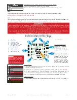
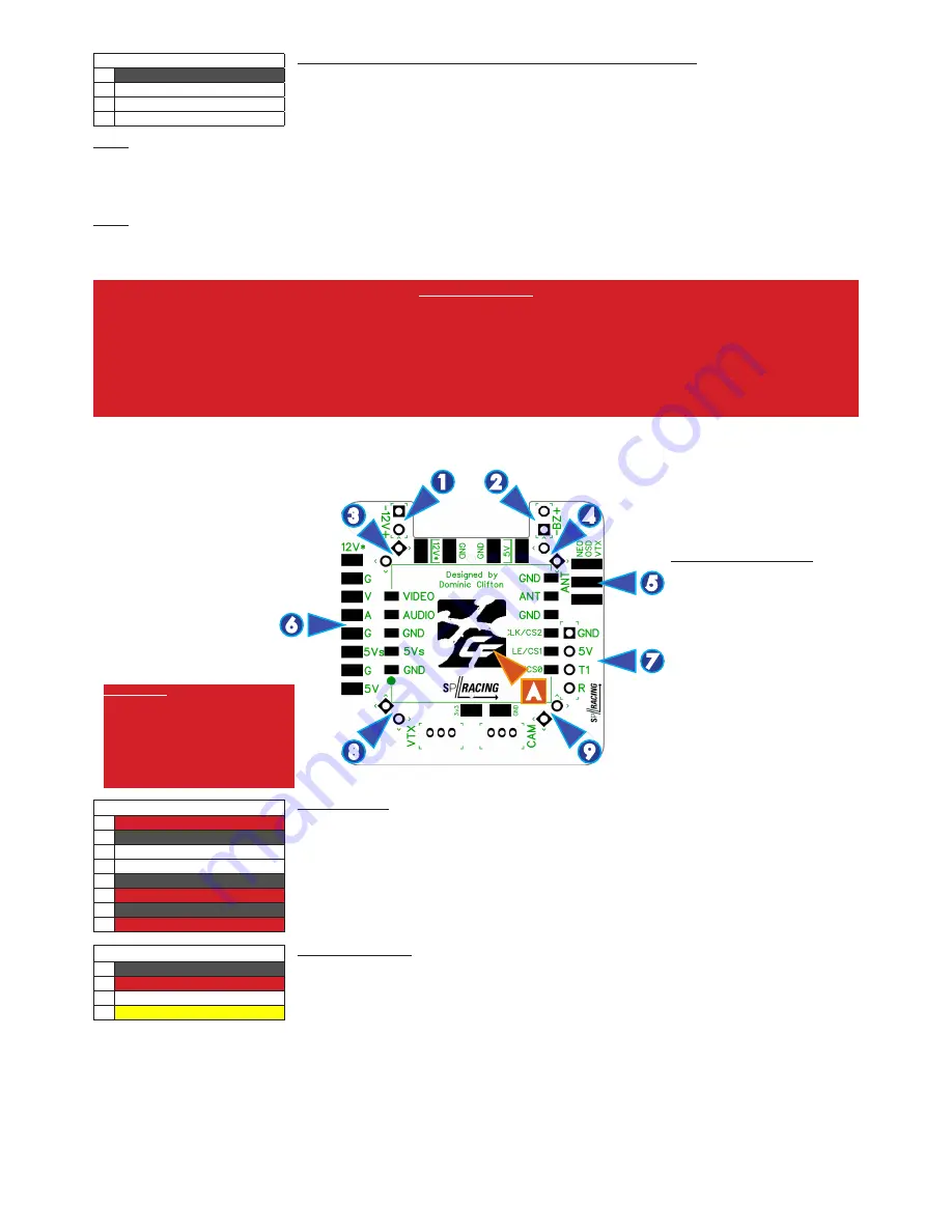
NEO OSD/VTX (Top)
1. 12V output.
2. Buzzer pads.
3. 12V-from-FC pads.
4. Buzzer-from-FC pads.
5. SMA PCB Mount Jack pads
for antenna. (2 more on
reverse).
6. External VTX pads.
7. UART1 break-out pads.
8. 5V-from-FC pads.
9. UART1-from-FC pads.
A. VTX Module
IMPORTANT
Never power on the VTX module
without an antenna connected or
with a damaged antenna. Doing so
will destroy the VTX module.
Inspect your antenna after any crash.
1
2
5
7
4
3
6
8
9
A
I2C/UART3/UART4 socket
(14)
1
n
12v*
2
n
GND
3
n
VIDEO OUT
4
n
AUDIO IN
5
n
GND
6
n
5v (Switchable)
7
n
GND
8
n
5v
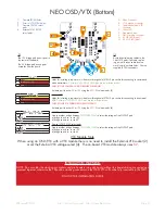
External VTX Pads
Use these pads for making solder connections to an external VTX. Note you may find the External VTX socket
on the bottom of the board more convenient.
The voltage on the
12V
pin depends on the 3S/12V selector on the NEO board. See the
3S WARNING
.
The
5Vs
pad is switchable by the FC. Power the VTX module or External VTX can be controlled by the FC. It
will be either ON or OFF. Cleanflight has a feature that allows a 5V VTX to be turned ON/OFF remotely.
If you have a microphone with AUDIO output, connect the MIC Audio out signal to the AUDIO pad.
I2C/UART3/UART4 socket
(14)
1
n
GND
2
l
5v
3
l
TXD (T1)
4
l
RXD (R1)
UART1 breakout-pads.
Use these convenient pads to connect UART-based devices such as Bluetooth, GPS, NFC, WIFI modules, etc.
STACKING CONNECTORS
The 4 pairs of *-from-FC-pads
(3,4,8,9) are for stacking onto
the NEO FC/PDB. They have
the same signals as the FC/PDB
board.
Fit the very-low-profile stacking
PINS to these pads, facing down-
wards. Solder them in from the
Top so that all the pins are on the
bottom of the OSD/VTX board..
Fit the very-low-profile stacking
SOCKETS to the NEO, facing up-
wards. Solder them in the Bottom
of the NEO so all sockets face up.


