SPRacingF3NEO
http://seriouslypro.com - http://cleanflight.com
Page 8
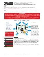
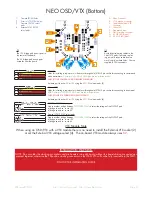
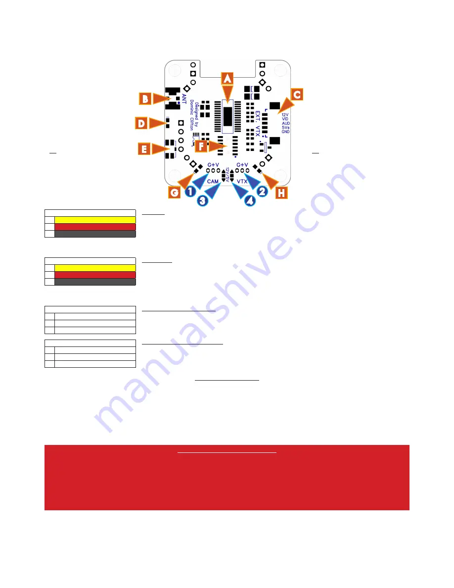
NEO OSD/VTX (Bottom)
1. Camera JST-ZH holes.
2. External VTX JST-ZH holes.
3. Camera 12V/5V select
pads.
4. External VTX 12V/5V
select pads.
A. Video Processor
B. u.FL Antenna connector
C. Picoblade external VTX
connector.
D. White LED.
E. Side-press button.
F. NEO stacking connector.
G. 5V OK LED (Green).
H. 3.3V OK LED (Blue).
TIP
The 12V bridge pad arrows point to
the center of the board.
The 5V bridge pad arrows point
outwards from the board.
CAMERA 5V/12V SELECT
(3)
1
p
12V
2
n
OUTPUT
3
q
5V
CAMERA 12V/5V select pads
Create a solder bridge between
TWO PADS ONLY
to select the voltage of the OUTPUT pad.
a) bridge
p
and
n
to use 12V.
b) bridge
n
and
q
to use 5V.
3
4
1
2
G
H
E
B
C
D
A
F
External VTX 5V/12V SELECT
(4)
1
p
12V
2
n
OUTPUT
3
q
5V
External VTX 12V/5V select pads
Create a solder bridge between
TWO PADS ONLY
to select the voltage of the OUTPUT pad.
a) bridge
p
and
n
to use 12V.
b) bridge
n
and
q
to use 5V.
CAMERA
(1)
1
l
VIDEO
2
l
POWER (12V or 5V)
3
l
GND
CAMERA
Holes for installing a top-mount or side-mount through hole JST-ZH 3 pin socket for connecting to camera and
video transmitters.
Center pin is POSITIVE, GND pins are towards the button.
CHECK YOUR CAMERA WIRING BEFORE POWERING.
Set each port to either
5V
or
12V
using the
5V/12V
selector pads (3).
External VTX
(2)
1
l
VIDEO
2
l
POWER (12V or 5V)
3
l
GND
External VTX
Holes for installing a top-mount or side-mount through hole JST-ZH 3 pin socket for connecting to an external
VTX.
Center pin is POSITIVE, GND pins are towards the button.
CHECK YOUR VTX WIRING BEFORE POWERING.
Set each port to either
5V
or
12V
using the
5V/12V
selector pads (4).
TIP
Avoid direct-soldering cables to the
CAM/VTX pads if possible, replac-
ing a worn/broken cable due to a
crash is hard on these holes. Use the
supplied JST-ZH connectors.
VTX Module Note
When using an OSD/VTX with a VTX module there is no need to install the External VTX socket (2)
or set the External VTX voltage select (4). The on-board VTX module always uses
5V
.
INSTALLATION WARNING
NOTE: Do not solder the stacking pin sockets and pin headers into each board without the boards being connected and
pressed together, otherwise the 12position stacking connector on the OSD/VTX will not be fully inserted into the NEO.
FOLLOW THE INSTALLATION GUIDE


