Q: I have no LEDs on at all.
A: Check 5v supply. (Battery Charged?, USB cable damaged?)
Q: The status LED never lights or is always on.
A: Follow recovery procedure in the configurator. Likely caused by flashing wrong firmware. Could also be
caused by stuck-down BOOT switch - check button for dirt, etc.
Q: Unable to connect and a repeating light sequence occurs on the activity LED.
A: Check the Cleanflight manual for how to interpret the error code (count the long flashes).
Q: Unable to connect to the board (and status LED shows non-repeating pattern at boot-up).
A: Close all Chrome browsers and Chome apps, retry. COM Port drivers not installed? Try connecting via differ-
ent UART OR Reset the board to defaults using buttons OR reflash firmware using ‘full chip erase’. (Likely caused
by mis-configuration of ports).
Q: Transponder code not recognised by receiver.
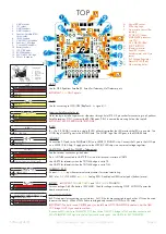
A: Check transponder enable bridge. Check IR LED orientation and light beam exit path. Ensure transponder
feature enabled in software. Ensure transponder code correctly configured.
Q: The COM port does not show up after flashing firmware.
A: Wrong firmware was flashed; Use SPRacingF4EVO target and follow recovery steps in the Cleanflight Configu-
rator firmware flasher to restore the firmware.
Q: The receiver tab does not show any activity.
A: Check configuration tab - receiver mode. Center sticks, configure endpoints and trim on transmitter. Check
ports tab if using Serial RX. Check wiring. Check S/R bridge, check T2/TLM bridge.
Q: You have a problem not listed here.
A: Reset and/or upgrade the firmware, try again, report issues via the forums - links are in the configurator on
the ‘Documentation & Support’ tab. Before contacting your retailer reflash with latest CLEANFLIGHT and double
check - perhaps the firmware you are using is old or incorrect?
Q: Only 5V LED lights up, No BLUE 3V LED or RED STATUS LED.
A: Most common cause is misconnection or short of VBAT pins - FC will be destroyed! Check for short in Spek-
trum Satellite cable if using Spektrum Satellite RX. Always caused by destroyed CPU or overloaded/shorted
voltage regulator.
Transponder
The SPRacingF4EVO features a IR LED transponder system. For optimum performance ensure you read the follow-
ing section.
Mounting - Ensure that the IR LED can shine light from its installed location onto the track-side receiver, unobstruct-
ed. e.g. ensure that props, motors, arms, etc, are not in the way of the light shining from the LED.
Orientation - Ensure the LED points outwards from the aircraft towards the track-side receivers. The more receivers
you use the better the code reception will be.
Verifying operation - Ensure that the TRANSPONDER feature is enabled in Cleanflight. Ensure that the correct
pads of the IR/LED SELECT solder pads are bridged with solder. Ensure that the TRANSPONDER code has been
configured via the Race Transponder configuration section in the Cleanflight Configurator. Once this is done you
can use a CMOS/CCD camera without IR block pointed directly at the IR LEDs and you should see them pulsing.
A mobile phone camera works well for this, your FPV camera and screen/goggles may be OK if it doesn’t block
IR light.
Once you have verified that the IR LED pulses IR light then you can scan your SPRacingF4EVO past one of the
iLAP receivers. The iLAP receiver just needs power, no software configuration is required to verify that the code is
working.
The first time the iLAP receiver can read the transponder code the LAP light will pulse once, while the iLAP receiver
can read the code then the activity light (ACT) will be flashing.
SPRacingF4EVO
http://seriouslypro.com - http://cleanflight.com
Page 11


