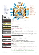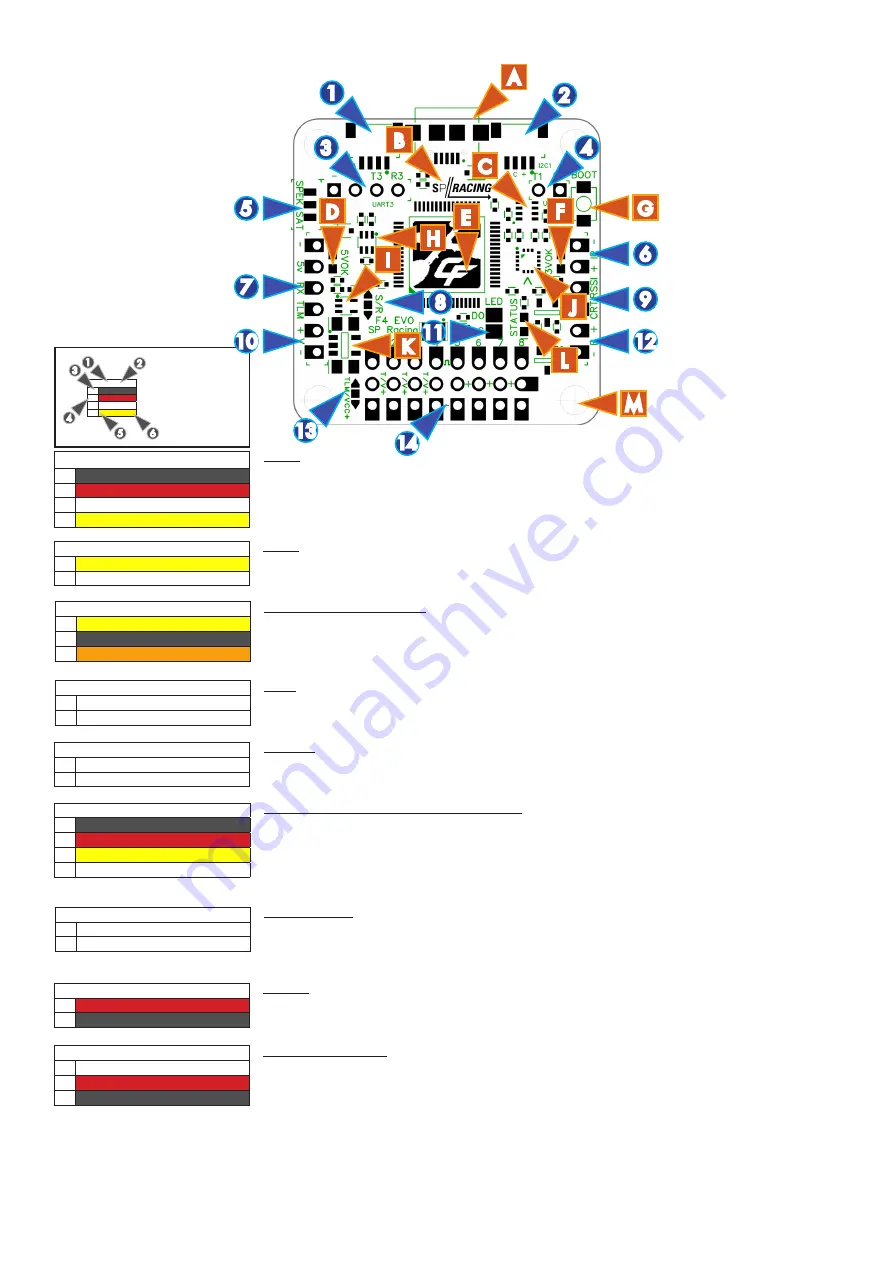
TOP
1.
UART4 socket.
2.
I2C socket.
3.
UART3 headers.
4.
UART1 headers.
5.
Spektrum Satellite JST-ZH
socket holes.
6.
IR LED headers.
7.
UART2 RX/TLM headers.
8.
Spektrum / RX bridge.
9.
Current/RSSI headers.
10. Battery headers.
11. LED STRIP pads.
12. BUZZER headers
13. ESC-TLM/VCC bridge
14. PWM 1-8 headers.
7
K
RX/TLM
(7)
1
n
GND
2
l
5v
3
l
RX - U2/RXD -- Serial RX/PPM
4
l
TLM - U2/TXD or U5/S.PORT/HoTT
UART2/PPM - Serial RX or PPM RX + Telememetry
See the receiver connection guide below.
Pin 4 is EITHER connected to UART2 TXD or to a bi-directional inverter on UART5.
Use UART2 for telemetry when the T2/TLM bridge is set to T2.
Use UART5 for telemetry when the T2/TLM bridge is set to TLM.
H
SPRacingF4EVO
http://seriouslypro.com - http://cleanflight.com
Page 4
Table Legend
1. Port name
2. Port number
3. PCB marker / Pad
shape
4. Pin number
5. Signal Name
6. Signal Color
UART2
(2)
1
l
GND
2
VIN
3
TXD/SWDCLK
4
RXD
3
5
1
6
2
4
A. MicroUSB socket.
B. SP Racing Logo.
C. Air pressure sensor (Ba-
rometer).
D. 5V OK LED (Green)
E. STM32F405 processor
with FPU.
F. 3.3V OK LED (Blue)
G. BOOT BUTTON
H. Telemetry Inverter
I.
Serial RX Inverter
J.
Accelerometer and Gyro
sensor.
K. 3v3 Voltage Regulator.
L. Status OK LED (Red)
M. M3 mounting holes.
14
3
5
4
E
6
Spektrum Satellite
(5)
1
l
RXD (R3)
2
l
GND
3
l
3.3v
Spektrum Satellite socket holes.
Holes ready to install a top-mount or side-mount through hole JST-ZH 3 pin socket for connecting to a Spektrum
Satellite receiver. PIN 1 is nearest the RX/TLM pads, PIN3 is nearest the mouning hole at the top-left.
IMPORTANT SEE S/R BRIDGE INSTRUCTIONS.
BATTERY
(10)
1
l
+V
2
n
V-
BATTERY -
IMPORTANT:
DOUBLE CHECK
and
TRIPLE CHECK
POLARITY!
For connecting a 2-6S LiPo battery (25V MAX). Used for voltage monitoring ONLY. Will NOT power the
board or accessories.
CURRENT / RSSI
(9)
1
l
CURRENT (CRT)
2
l
RSSI
CURRENT / RSSI
Current -
0 - 3.3v
input from external current sensor for current monitoring.
RSSI is for
0 - 5v
PWM RSSI or
0 - 3.3v
Analog RSSI - Disabled until RSSI select pads (bottom) are set.
PWM 1-8 ESC/SERVO OUTPUTS
(14)
1
l
PWM/ONESHOT125
2
l
Pads 1-4 are Switchable, 5-8 always VIN
3
n
GND
ESC/SERVO OUTPUTS.
8x3 Pin headers for connecting servos/motors. ALL
VIN
holes are connected to each other. VIN can be used
to power the board. When VIN-5v Pads are bridged only connect OUTPUTs to
VIN
holes.
IMPORTANT: The first 4 round CENTER pads (on the left) are NOT CONNECTED by default. Set the TLM/
VCC bridge ONLY if you need to use them.
If you have ESCs that have TELEMETRY OUT then set the TLM/VCC bridge to TLM and then connect each
ESC’s TELEMETRY OUT signal to the first four round center pads. Use UART4 for ESC TELEMETRY.
UART1
(4)
1
n
RXD (R1)
2
l
TXD (T1)
UART1
Use for connecting to OSD/GPS/BlueTooth.
5v
signals
OK
.
IR LED
(6)
1
n
IR -
2
l
IR + / LED Strip
IR LED
IR + (Pin 2, ROUND) is used to a single IR LED - either direct-solder the LED or attach the LED via a cable. The
LONG leg of the LED goes in the ROUND hole. The SHORT leg of the LED goes in the SQUARE hole.
A
M
10
9
12
UART3
Use for GPS, Spektrum Satellite RX, SmartPort Telemetry, HoTT telemetry, etc.
IMPORTANT:
3.3v
ONLY signals
.
UART3
(3)
1
n
GND
2
l
VIN
3
l
TXD (T3)
4
l
RXD (R3)
G
1
2
L
C
F
B
D
8
I
13
J
11
LED STRIP
(11)
1
n
Data Out (DO)
2
n
Ground (G)
LED STRIP
Connect the DO pad to the DIN (Data DIN) on a WS2812 RGB LED strip. Connect the G pad to the GND pin
on a WS2812 LED Strip. Supply power to the WS2812 LED strip via an external voltage regulator.


