Receiver Connections
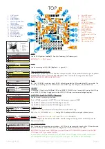
The F4 EVO has two receiver sockets (RX/TLM and Spektrum Sat) and two receiver configuration bridges (S/R
and T2/TLM).
Examples of PPM receivers:
FrSky D4R, FrSky D8R
Examples of Serial RX receivers:
FrSKY X4RSB, XS4 (SBus), Spektrum AR6270T (Spektrum), Graupner GR24 (HoTT), Futaba R3008SB
(SBus)
Examples of Spektrum Satellite receivers:
Spektrum Quad Race Serial Receiver w/Diversity - SPM4648, DSMX Remote Receiver -
SPM9645
The following table indicates where different types of receivers should be connected and what the bridges should
be set to.
RX
Telemetry
T2/TLM
Bridge
S/R Bridge RX Port Pin 3
TLM/R2
RX Port Pin 4
TLM/T2
Spektrum
Sat Port
RX
TELEMETRY
PPM
FrSky/LTM/etc
T2
R *1
RX Out
Telemetry Out
UNUSED
PPM
UART2
FrSky Serial RX
S.PORT
TLM
R *1
RX Out
S.PORT
UNUSED
UART2
UART5
Graupner HoTT RX
HoTT
-
R *1
RX Out
UNUSED
UNUSED
UART2
UART1/3/4 *3
Single-Wire RX+TLM
IBUS/SRXL/CRSF
T2
R *1
UNUSED
RX out/TLM in *4
UNUSED
UART2
UART2 *4
Dual-Wire RX+TLM
IBUS/SRXL/CRSF
T2
R *1
RX Out *5
TLM in *5
UNUSED
UART2
UART2 *5
Spektrum Satellite RX
-
-
S *2
UNUSED
UNUSED
RX OUT
UART3
-
*1 Default - no soldering needed.
*2 Cut trace between SQUARE and ‘R’ TRIANGLE then solder ‘S’ TRIANGLE to SQUARE - See below.
*3 UART5, when used, is ALWAYS INVERTED. S.PORT is inverted. HoTT is NOT and cannot be used on the same
UART port as the receiver signal. UART2 is used for receiver signals and UART5 cannot be used for HoTT so use
any other free serial port for HoTT telemetry - i.e UART1,3 or 4.
*4 Some receivers support one-wire bi-directional transfer of RX channels to the FC and Telemtery from the FC to
the Receiver. e.g. IBUS/SRXL/CRSF. If you receiver supports this use the UART2 TX pin only.
*5 Some receivers support incoming RX data and outgoing Telemetry at the same speed and port settings, using
two wires.
S/R bridge.
The S/R bridge is connected by default to the ‘R’ side.
ONLY SPEKTRUM SATELLITE RECEIVER USERS
should
change or set this jumper. There is a small electrical trace between the SQUARE pad and the right-hand side ‘R’
TRIANGLE pad. This trace MUST be cut, carefully and without slipping, and the left-hand side ‘S’ TRIANGLE must
be soldered to the center SQUARE pad before connecting your Spektrum Satellite receiver to the Spektrum
Satellite receiver port. After cutting the trace, use a multimeter to check there is no connectivity between the center
SQUARE pad and the right-hand ‘R’ TRIANGLE pad.
When set to S the S/R bridge isolates the inverter from the CPU and enables Spektrum Bind support on UART2.
When set to R the S/R bridge connects the inverter to the CPU and allows the CPU to enable/disable the inverter
as required by the receiver.
SPRacingF4EVO
http://seriouslypro.com - http://cleanflight.com
Page 6


