


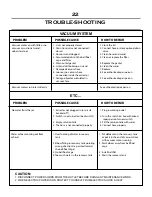

TIP
RATIO
oz/gal.
mL/L
Tan
102:1
1.25
7.8
Orange
75:1
1.70
10.5
Turquoise
60:1
2.15
13.3
Pink
43:1
3.00
18.6
Light Blue*
33:1
3.90
24.2
Brown
28:1
4.55
28.2
Red
22:1
5.80
36.0
White
18:1
7.00
43.4
Green
16:1
7.90
49.0
Blue
13:1
9.80
60.8
Yellow
9:1
14.80
91.8
Black
6:1
20.15
124.9
Purple
5:1
27.80
172.4
Gray
4.1
31.60
195.9
None
3.6:1
35.00
217.0
1 GPM/3.8 LPM
18
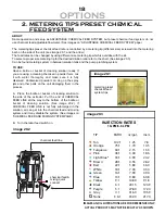
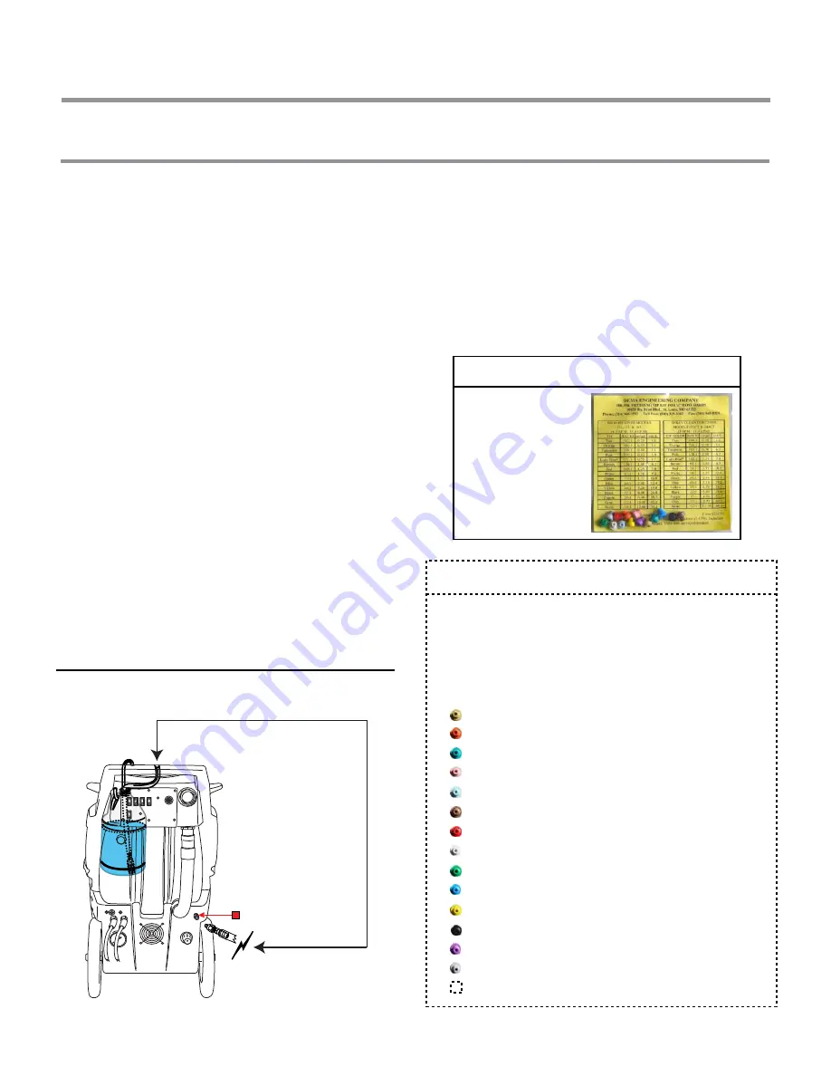
ABOUT:
Same operation and setup as ADJUSTABLE CHEMICAL FEED SYSTEM, but preset chemical feed system do not
use chemical feed adjustable flowmeter. (See images on “ADJUSTABLE CHEMICAL FEED SYSTEM” page)
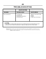
The metering tips preset chemical feed rate is controlled by a metering tip (different size) screwed into the metering
barb on the side of the unit. (see image 20.1, and the arrow)
The feed rates can be changed by using different size metering tip which is availabe with the kit.
To select a proper size metering tip for the desired dilution ratio refer to the chart. (See image 20.3)
Can be found metering system in between solution tank and the pump plumbing system.
OPTIONS
metering preset
chemical feed
system tips
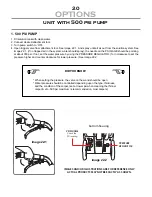
TO USE:
Have a bottle or bucket of cleaning solution ready. If
you are using a cleaning chemical in powder form, mix
it with water thoroughly and make sure it is fully
dissolved. Undissolved powder can clog up the spray
jets and other parts on the unit damaging them in the
process.
A. Place the bottle or bucket of cleaning solution to
the side of the extractor. Put the end of CHEMICAL
FEED LINE all the way to the bottom of the bottle or
bucket of cleaning solution. (See image 20.2). If
CHEMICAL FEED LINE is not fully submerged in the
solution, air can get into the chemical feed and mixing
system and it may disable the system. (See images on
“CHEMICAL FEED AND MIXING SYSTEM PAGE)
B. Turn chemical feed switch on.
INJECTION RATES
2. METERING TIPS PRESET CHEMICAL
FEED SYSTEM
IMAGES AND ILLUSTRATIONS ARE FOR REFERENCE ONLY.
ACTUAL PRODUCTS MAY NOT BE EXACTLY AS SHOWN.
image 20.1
image 20.2
image 20.3
chemical feed line
chemical feed &
mixing quick
connect
Summary of Contents for CF-100 Series
Page 2: ......


