2- 1
TEL-14 TWO-CHANNEL TELEPHONE INTERFACE
2
INSTALLATION
INTRODUCTION
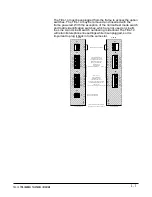
This chapter describes the TEL-14 two-channel auto-nulling
telephone interface and its installation in the matrix, including
setting internal option switches, wiring to external devices,
operation of the front panel controls and indicators, and electrical
and mechanical specifications. The following subjects are covered in
this chapter:
•
Description
•
Installation in an interface frame
•
Wiring
•
Setup
•
Configuration
The TEL-14's panel controls and internal option switches can select
any one of a large number of modes of operation for the TEL-14. For
this reason, this section describes each option switch individually,
and then describes the installation settings for five of the TEL-14's
most common modes:
•
Intercom-station telephone access
•
Self-service dial-in
•
Manual call screening
•
Intercom-to-intercom
•
Party line dial-in
Note: Other configurations are possible, in addition to the
configurations described here. However, certain configurations may
result in undesirable crosstalk, as a result of the limitations of the TEL-14's
circuitry. For example, consider a news reporter who calls into the matrix.
You would like to provide the reporter with a program feed, and at the
same time route his voice in through the matrix to a live broadcast. However,
the TEL-14 cannot perfectly isolate his talk from his listen, so some
of his outgoing program feed may leak into his incoming voice.
Note: When using the TEL-14 with a speaker station, keep the panel mic gain
low. In
general, keep all gain controls set to a level which is acceptable, but not excessive.
Warning: The TEL-14 works with POTS (Plain Old Telephone Service) Central
Office
(CO) lines. Analog station lines from some PABXs are not compatible.
Summary of Contents for ECLIPSE TEL-14
Page 6: ......


