background image

V- 

Series XLR-7M Option 


Fitting the XLR-7M Headset Connector Assembly to Desktop Panels


Before fitting the XLR-7M Headset Connector Assembly the panel must be 
completely disconnected from any cabling.  Place the panel on a clear 
workspace suitable for antistatic precautions. 


Step 1


Note: Record whether the panel has been build for desktop use or for 
attachment to a wall to ensure the front panel is replaced in the correct 
orientation.


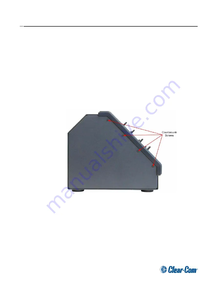
Remove the eight countersunk screws holding the front of the panel on.  The 
countersunk screws are located on the ends of the panel, four on each end 
(Figure 18).


Figure 18: Desktop Panel Retaining Screws


Remove and retain all the screws and remove the front panel assembly.  The 
cables connecting the front panel electronics to the main PCB are long 
enough to allow the panel front to be removed without having to unplug any of 
the cables. 


PN 810405Z Rev. C 

12


Summary of Contents for XLR-7M

Page 1: ...eady fitted with male XLR 4M headset connectors They do not apply to panels fitted with female headset connectors Converting the XLR 4M to XLR 7M requires the following items 1 x XLR 7M Headset Connec...

Page 2: ...ere see Figure 1 If it is not fitted in the cradle proceed to step 2 Figure 1 Power Supply in Cradle on Rack Mount Panel Unlock the power connector from the panel by turning the outer ring anticlockwi...

Page 3: ...the front panel assembly must be removed to gain access to change the headset connector If the panel is a 2 RU panel then the front panel assembly need not be removed If the front panel does not need...

Page 4: ...5 Screws on Bottom of Chassis Pull the front panel assembly away from the chassis to give access to the connectors and cables Step 6 Disconnect the microphone and main board connection cables from the...

Page 5: ...e Front Panel Audio Card and gently pull the audio card away from the Headset Connector Assembly Step 7 Remove the 2 hex pillars securing the Headset Connector Assembly to the front panel assembly usi...

Page 6: ...ep 8 Figure 9 Headset Connector Assembly with Hex Pillars Removed Remove the existing XLR 4M Headset Connector Assembly from the front panel assembly Figure 10 Panel with Headset Connector Assembly Re...

Page 7: ...to ensure that the PCB is aligned so that the hex pillars will clear the PCB when they are in place If the assembly requires adjustment please refer to Appendix A Figure 11 XLR 7M Assembly Alignment...

Page 8: ...ure 12 Fit the XLR 7M Headset Connector Assembly Fit the hex pillar on the left only as shown in Figure 13 below Move the loose assembly to allow the pillar to be tightened Figure 13 Fit Left Pillar B...

Page 9: ...V Series XLR 7M Option Step 11 Fit and tighten the pillar on the right as shown in Figure 14 below Figure 14 Fit Right Pillar Beside Assembly 9 PN 810405Z Rev C...

Page 10: ...is turned clockwise the grub screw will move out of the connector and lock with the black plastic moulding Do not over tighten the grub screw as this is very difficult to refit once the PCB is assembl...

Page 11: ...sis before fitting the screws Refit the countersunk screws to the rear of the mounting ears Replace the four countersunk screws on the bottom of the chassis Refit the 2 encoder knobs to the Main and A...

Page 12: ...for attachment to a wall to ensure the front panel is replaced in the correct orientation Remove the eight countersunk screws holding the front of the panel on The countersunk screws are located on t...

Page 13: ...uring the Headset Connector Assembly to the mounting block Remove the Headset Connector Assembly Step 3 Before fitting the XLR 7M Headset Connector Assembly it should be checked to ensure that the PCB...

Page 14: ...t Position the XLR 7M Headset Connector Assembly on the mounting block and replace the two pozidrive screws Step 4 Figure 21 XLR 7M Headset Connector Assembly Attached to Mounting Block Replace the au...

Page 15: ...ed see Figure 18 Insert the microphone connector edge into position first then lower the headset connector into place Note Ensure that no cables are trapped before attempting to refit the screws Apply...

Page 16: ...dset Connector Assembly Adjust the PCB position to centralize the curved PCB edges with respect to the holes in the block and then retighten the grub screw by turning it clockwise Warning The grub scr...

Reviews: