


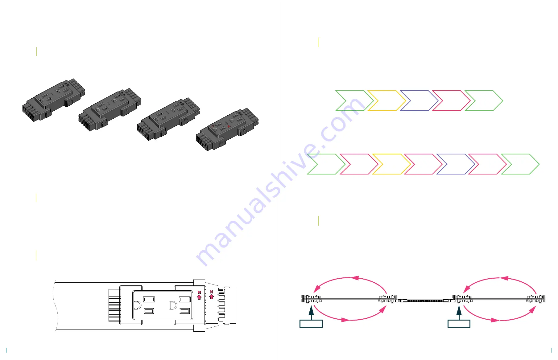
Attach the Duplexes in a Counterclockwise Direction
START
at the front-left position.
Continue in a counterclockwise direction.
Start in the same position on the next harness in line,
and continue with the sequence.
KEY CONCEPTS
3
1
2
4
BPDR_C1
BPDR_C2
BPDR_C3
BPDR_T24_C4
SENSOR ACTIVATED
CONTROL CIRCUIT
If you are installing this power system within the state of California,
you must comply with the California Title 24 regulations.
1
The duplex recepticals are designated as circuit 1, 2, 3, or 4.
The number is printed on each duplex.
Circuit 4 is the sensor activated control circuit.
2
Every duplex, harness, jumper, and infeed displays a North arrow.
The North arrows MUST point the same direction on all parts.
3
Title 24 Electrical Requirement:
HALF of the Duplexes on Each Harness Must be C4 Control Circuits
The duplexes must be attached to the harness in a specific order.
Arrange the duplexes in the correct order by following the sequence.
4
DUPLEX RECEPTICALS
TITLE 24 COMPLIANCE
NORTH
DUPLEX SEQUENCE
C1
C2
C3
C4
REPEAT
STANDARD SEQUENCE
C1
C2
C3
C4
C4
C4
REPEAT
TITLE 24 SEQUENCE
*
START
START
1st Harness
Jumper
2nd Harness
For installation questions call
210.648.2095
or email
customerservice@mycleardesign.com
4
5


